Antenna-deco film stack structure and display device including the same

a technology of display device and stack structure, which is applied in the direction of resonant antennas, identification means, instruments, etc., can solve the problems of signal interruption or impedance mismatch, the display device may not be able to achieve the desired image of the display device, and the display device may be hindered by the display device, so as to improve signaling efficiency and reliability

Active Publication Date: 2022-05-03
DONGWOO FINE CHEM CO LTD
View PDF15 Cites 0 Cited by
  • Summary
  • Abstract
  • Description
  • Claims
  • Application Information

AI Technical Summary

Benefits of technology

[0008]According to an aspect of the present invention, there is provided an antenna-deco film stack structure having improved signaling efficiency and reliability.
[0009]According to an aspect of the present invention, there is provided a display device including the antenna-deco film stack structure and having improved image quality.
[0029]In an antenna-deco film stack structure according to exemplary embodiments as described above, an antenna pattern may be disposed under a light-shielding portion of a deco film. Thus, the antenna pattern may be prevented from being viewed, and interference from a conductive pattern of a display device or a touch sensor may be reduced.

Problems solved by technology

Radiation interruption with respect to the antenna may be caused by the conductive patterns, and thus desired high frequency and high gain properties may not be easily obtained.
Further, when the display device includes a sensor member such as a touch sensor, signal interruption or impedance mismatching may be also caused by the sensor member.
If the antenna is viewed by a user, desired image of the display device may be hindered by the display device.

Method used


Image

  • Antenna-deco film stack structure and display device including the same
  • Antenna-deco film stack structure and display device including the same
  • Antenna-deco film stack structure and display device including the same

Examples


Embodiment Construction

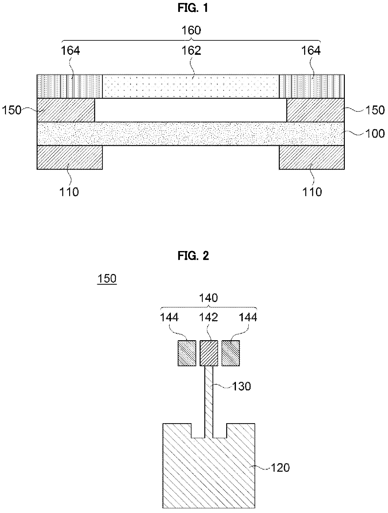
[0037]According to exemplary embodiments of the present invention, an antenna-deco film stack structure is provided. The antenna-deco film stack structure may include a deco-film and an antenna pattern disposed under the deco film, and may have improved radiation and optical properties. A display device including the antenna-deco film stack structure is also provided.

[0038]The term “stack structure” used herein includes an independent and integral single structure or a combined structure, and may also include an assembly of elements in a display device.

[0039]Hereinafter, the present invention will be described in detail with reference to the accompanying drawings. However, those skilled in the art will appreciate that such embodiments described with reference to the accompanying drawings are provided to further understand the spirit of the present invention and do not limit subject matters to be protected as disclosed in the detailed description and appended claims.

[0040]FIG. 1 is a...


PUM

PropertyMeasurementUnit
dielectric constantaaaaaaaaaa

Abstract

An antenna-deco film stack structure includes a deco film including a light-shielding portion and a transmissive portion, a dielectric layer facing the deco film, an antenna pattern disposed on an upper surface of the dielectric layer and disposed under the deco film, the antenna pattern being at least partially covered by the light-shielding portion, and a ground pattern on a lower surface of the dielectric layer to at least partially cover the antenna pattern. The deco film and the antenna pattern are combined to improve radiation reliability and optical property of the antenna pattern. A display device including the antenna-deco film stack structure is also provided.

Description

CROSS-REFERENCE TO RELATED APPLICATION AND CLAIM OF PRIORITY[0001]The present application is a continuation application to International Application No. PCT / KR2019 / 012802 with an International Filing Date of Oct. 1, 2019, which claims the benefit of Korean Patent Application No. 10-2018-0123823 filed on Oct. 17, 2018 at the Korean Intellectual Property Office, the disclosures of which are incorporated by reference herein in their entirety.BACKGROUND1. Field[0002]The present invention relates to an antenna-deco film stack structure and a display device including the same. More particularly, the present invention related to an antenna-deco film stack structure including a plurality of antenna patterns and a display device including the same.2. Description of the Related Art[0003]As information technologies have been developed, a wireless communication technology such as Wi-Fi, Bluetooth, etc., is combined with a display device in, e.g., a smartphone. In this case, an antenna may be co...

Claims


Application Information

Patent Timeline
Patent Type & Authority Patents(United States)
IPC IPC(8): H01Q1/38H01Q1/24H01Q1/52
CPCH01Q1/243H01Q1/38H01Q1/526H01Q1/48H01Q1/50H01Q1/22G09F9/30G02B5/20H01Q9/0407H01Q21/065H01Q1/422
Inventor OH, YUN SEOKRYU, HAN SUBHUH, YOON HO
Owner DONGWOO FINE CHEM CO LTD
Why Eureka
Try Eureka