High frequency film transmission line, antenna including the same and antenna-integrated image display device

a high-frequency film and transmission line technology, applied in the direction of resonant antennas, printed circuit non-printed electric components association, waveguides, etc., can solve the problems of insufficient suggestions, and achieve the effect of preventing the loss of signal between the plurality of antennas, low loss tangent, and low signal loss level

Active Publication Date: 2022-04-26
DONGWOO FINE CHEM CO LTD
View PDF14 Cites 0 Cited by
  • Summary
  • Abstract
  • Description
  • Claims
  • Application Information

AI Technical Summary

Benefits of technology

[0009]According to an aspect of the present invention, there is provided a high frequency film transmission line having improved signaling efficiency and reliability.
[0011]According to an aspect of the present invention, there is provided an image display device integrated with an antenna having improved signaling efficiency and reliability.
[0032]According to exemplary embodiments of the present invention, a film transmission line may include an electrode line disposed on a dielectric layer including a liquid crystal polymer (LCP) or a cyclo olefin polymer (COP). The LCP or COP may have remarkably low loss tangent relatively to other insulation or dielectric materials, and thus low signal loss level may be maintained even though a length of the electrode line is increased.
[0033]In some embodiments, a plurality of antennas may be connected by the film transmission line. Thus, signal loss between the plurality of the antennas may be prevented and a size of an antenna structure may be reduced. In some embodiments, the film transmission line and the antenna may be isolated from each other at different layers or different levels with respect to a display panel of an image display device. Thus, the transmission line may be arranged without spatial limitation by a display driving integrated circuit (IC) chip, a memory device, etc., disposed on a printed circuit board (PCB) of the image display device.
[0034]Therefore, signal loss through the transmission line may be reduced, and interference or disturbance by noises from a circuit device or an electronic device on the printed circuit board may be removed or reduced.

Problems solved by technology

Further, various wiring structures such as a resistor, a capacitor, a condenser, etc., may be included in the display device, and an antenna signal may interrupted or interfered by a noise from the circuit structure.
For example, Korean Published Patent Application No. 2016-0059291 discloses an antenna integrated in a display panel, however, fails to suggest sufficient solutions of the above-mentioned issues.

Method used


Image

  • High frequency film transmission line, antenna including the same and antenna-integrated image display device
  • High frequency film transmission line, antenna including the same and antenna-integrated image display device
  • High frequency film transmission line, antenna including the same and antenna-integrated image display device

Examples


experimental example 1

roperty Depending on a Dielectric Material and a Length of an Electrode Line

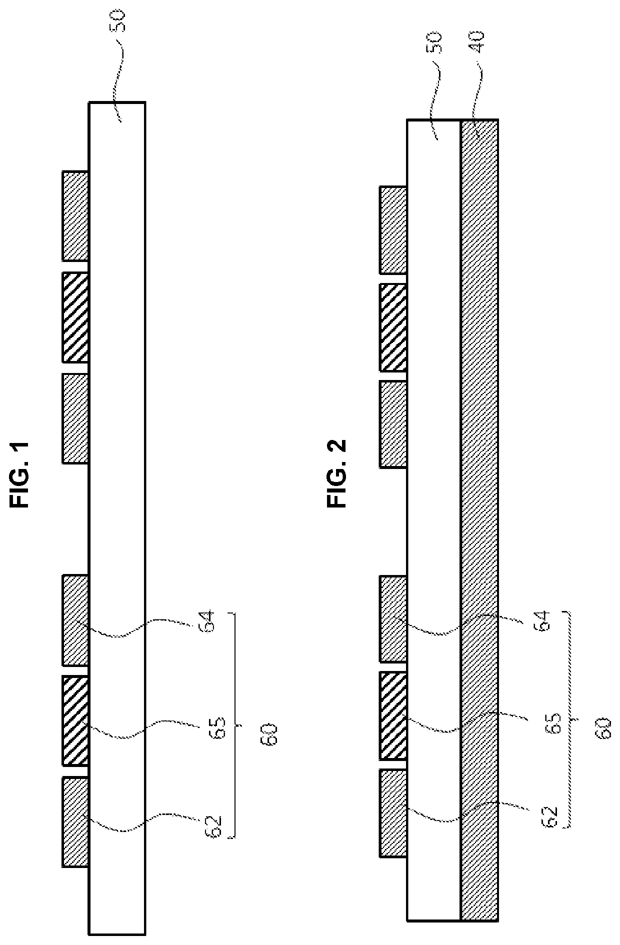
[0121]Electrode lines having a thickness of 0.24 μm and a width of 250 μm were formed using a silver-palladium-copper (APC) alloy on dielectric layers having a thickness of 50 μm and including different materials.

[0122]Specifically, LCP (dielectric constant: 3.0, loss tangent: 0.0008, Product name: R-F705S, Manufacturer: Panasonic), COP (dielectric constant: 2.25, loss tangent: 0.0008, Product name: ZF16, Manufacturer: ZEONEX), polyimide (PI) (dielectric constant: 3.0, loss tangent: 0.01, Product name: E1208 D500NM, Manufacturer: SK), polyethylene terephthalate (PET) (dielectric constant: 3.4, loss tangent: 0.002, Product name: SWOO, Manufacturer: SKC), polymethyl methacrylate (PMMA) (dielectric constant: 3.4, loss tangent: 0.002, Product name: WOO1AU60, Manufacturer: Sumitomo), triacetyl cellulose (TAC) (dielectric constant: 3.6, loss tangent: 0.013, Product name: KC2UAW, Manufacturer: Konica) and glass wer...

experimental example 2

roperty Depending on a Dielectric Material and a Frequency

[0125]An APC electrode line having a thickness of 100 μm, a width of 5 mm and a length of 40 mm was formed on the dielectric layers of Experimental Example 1.

[0126]Signal loss levels (S21) were measured by the same method as that in Experimental Example 1 while changing frequencies with respect to the electrode line. The results are shown in FIG. 9.

[0127]Referring to FIG. 9, in the dielectric layers including LCP and COP, S21 values were maintained as about −1.5 dB or more within the frequency from 20 to 30 GHz.


PUM

PropertyMeasurementUnit
frequencyaaaaaaaaaa
dielectric constantaaaaaaaaaa
lengthaaaaaaaaaa

Abstract

A film transmission line includes a dielectric layer including at least one of a liquid crystal polymer (LCP) structure or a cyclo olefin polymer (COP) structure, and an electrode line on the dielectric layer. A signal loss level (S21) defined of the film transmission line is −1.5 dB or more at a frequency in a range from 20 GHz to 30 GHz. The film transmission line may be applied to a high frequency thin film antenna and an image display device.

Description

CROSS-REFERENCE TO RELATED APPLICATION(S)[0001]This application claims the benefit under 35 USC § 119(a) of Korean Patent Application No. 10-2018-0102865 filed on Aug. 30, 2018, in the Korean Intellectual Property Office, the entire disclosure of which is incorporated herein by reference for all purposes.BACKGROUND1. Field[0002]The present invention relates to a high frequency film transmission line, an antenna including the same and an antenna-integrated image display device.2. Description of the Related Art[0003]As information technologies have been developed, a wireless communication technology such as Wi-Fi, Bluetooth, etc., is combined with a display device in, e.g., a smartphone. In this case, an antenna may be combined with the display device to provide a communication function.[0004]Mobile communication technologies have been rapidly developed, an antenna capable of operating an ultra-high frequency communication is needed in the display device. Further, various communicatio...

Claims


Application Information

Patent Timeline
Patent Type & Authority Patents(United States)
IPC IPC(8): H01Q1/38H01P3/08H01Q1/22H05K1/18H05K1/02
CPCH01P3/082H01Q1/22H01Q1/38H05K1/0243H05K1/181H01Q1/50H01Q1/52H01Q1/48H01P11/003H01P3/081C09K2019/0448C09K2019/2078C09K19/322C09K19/3809C09K19/321C09K2219/11H01Q1/243H01Q9/0407H01Q1/364H05K1/189H05K1/147H05K2201/10098H01Q1/46
Inventor HUH, YOON HORYU, HAN SUBOH, YUN SEOK
Owner DONGWOO FINE CHEM CO LTD
Why Eureka
Try Eureka