Supercharge Your Innovation With Domain-Expert AI Agents!

Counter UAV drone system using electromagnetic pulse

a counter-uav and electromagnetic pulse technology, applied in the direction of vehicle position/course/altitude control, process and machine control, instruments, etc., can solve the problems of limited protection of electronics from electromagnetic pulses, serious impairment of reliability, and especially vulnerable electronic devices, especially computer-based devices

Active Publication Date: 2022-07-05
THE UNITED STATES OF AMERICA AS REPRESENTED BY THE SECRETARY OF THE NAVY
View PDF9 Cites 0 Cited by
  • Summary
  • Abstract
  • Description
  • Claims
  • Application Information

AI Technical Summary

Benefits of technology

The invention is about a device and method to use a single drone to stop multiple drones from attacking. The device generates an electro magnetic pulse to disable the electronics of the approaching drones. The drone that is sacrificial (a drone meant to protect the others) is controlled by a remote pilot and flies into the middle of the drone swarm. The device is attached to the sacrificial drone and is activated to disrupt the electronics of the approaching drones.

Problems solved by technology

Electronic devices, especially computer based devices, are particularly vulnerable to EMP effects, as they are largely composed of high density Metal Oxide Semiconductor (MOS) devices, which are very sensitive to exposure to high voltage transients.
Even if the pulse itself is not powerful enough to produce total destructive damage, the power supply in the equipment will readily supply enough energy to complete the destructive process.
Wounded devices may still function, but their reliability will be seriously impaired.
Shielding electronics by equipment chassis provides only limited protection, as any cables running in and out of the equipment will function as an antenna, in effect guiding the high voltage transients into the equipment.
Other electronic devices and electrical equipment may also be destroyed by the EMP effect.
Telecommunications equipment can be highly vulnerable, due to the presence of copper leads / cables between devices.
Receivers of all varieties are particularly sensitive to EMP, as the highly sensitive miniature high frequency transistors and diodes in such equipment are easily destroyed by exposure to high voltage electrical transients.
Therefore, radar and electronic equipment, satellite, microwave, UHF, VHF, HF and low band communications equipment and video equipment are all potentially vulnerable to the EMP effect.
Given this, the activation of the interceptor UAV EMP generating device may also interrupt, or completely destroy, any wireless communication from a remote pilot commanding the incoming swarm.

Method used


Image

  • Counter UAV drone system using electromagnetic pulse
  • Counter UAV drone system using electromagnetic pulse
  • Counter UAV drone system using electromagnetic pulse

Examples


Embodiment Construction

[0021]In general, the present invention is directed to airborne security measures and more specifically to a device and method to defeat in total a plurality of approaching Unmanned Aerial Vehicles (UAVs) with a single sacrificial intercepting drone. In a preferred embodiment of the invention the intercepting drone may be configured with an attached Electro-Magnetic Pulse (EMP) generating device capable of producing a sufficiently intense EMP burst to completely disable all approaching UAVs.

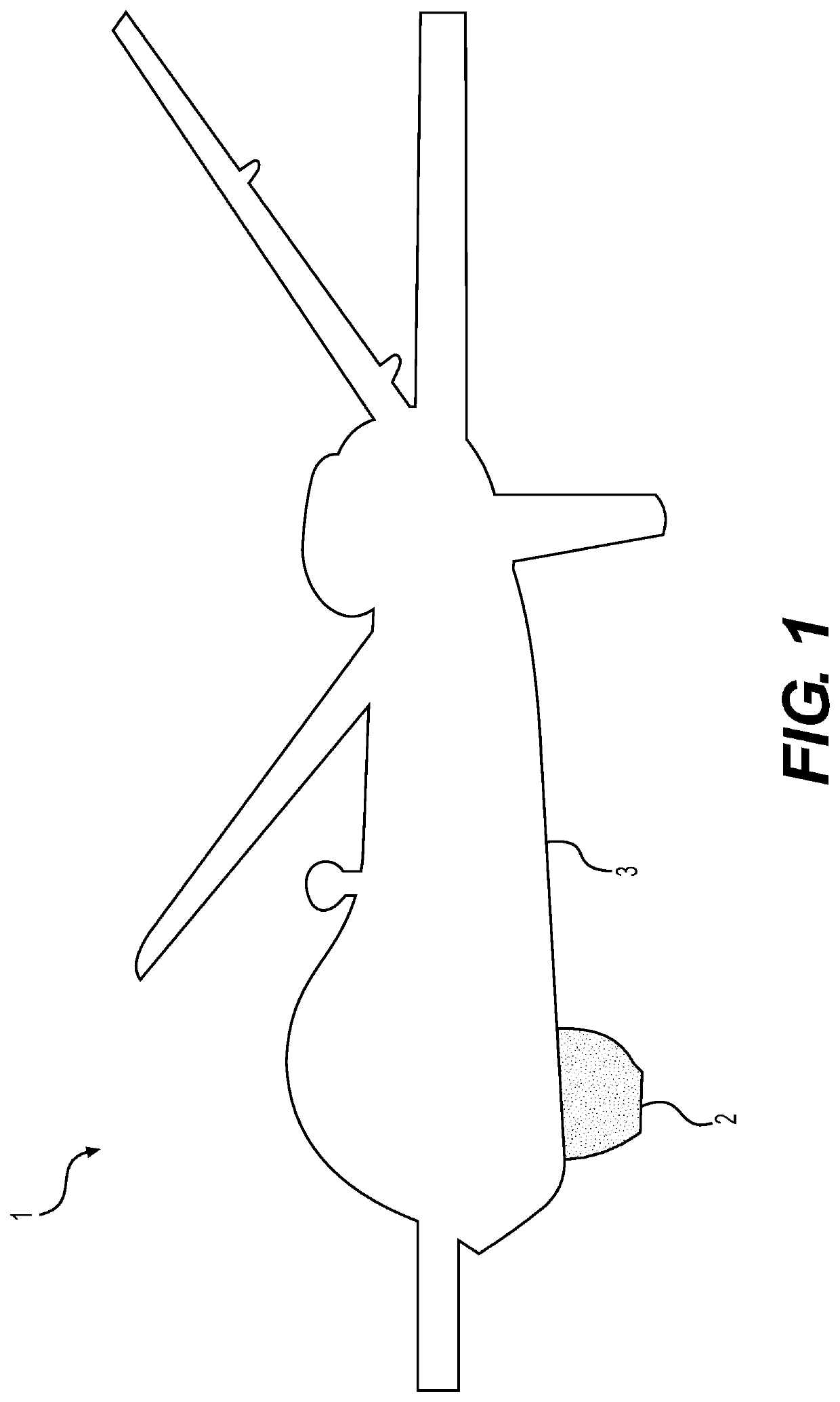
[0022]One embodiment of the present invention is shown in FIG. 1 depicting an unmanned aerial vehicle (UAV) 1 with an Electro-Magnetic Pulse (EMP) generating device 2 attached to the UAV's fuselage region 3. The UAV may be configured with the necessary hardware (not shown) to receive wireless communication commands from a remote pilot to both navigate the UAV and detonate the EMP device.

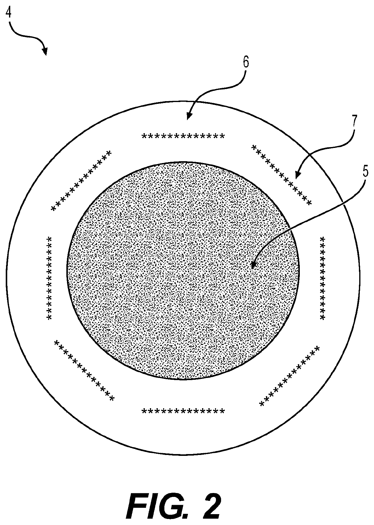
[0023]FIG. 2 shows a cross sectional view of one embodiment of the Electro-Magnetic Pulse (EMP) generating devi...


PUM


Abstract

In general, the present invention is directed to airborne security measures and more specifically to a device and method to defeat in total a plurality of approaching Unmanned Aerial Vehicles (UAVs) with a single sacrificial intercepting drone. In a preferred embodiment of the invention the intercepting drone may be configured with an attached Electro-Magnetic Pulse (EMP) generation device capable of producing a sufficiently intense EMP burst to completely disable all approaching UAVs.

Description

CROSS REFERENCE TO RELATED APPLICATIONS[0001]This application claims priority to U.S. Provisional Application Ser. No. 62 / 849,312 filed on May 17, 2019, the disclosure of which is expressly incorporated herein by reference.STATEMENT REGARDING FEDERALLY SPONSORED RESEARCH OR DEVELOPMENT[0002]The invention described herein was made in the performance of official duties by employees of the Department of the Navy and may be manufactured, used and licensed by or for the United States Government for any governmental purpose without payment of any royalties thereon. This invention (Navy Case 200,611) is assigned to the United States Government and is available for licensing for commercial purposes. Licensing and technical inquiries may be directed to the Technology Transfer Office, Naval Surface Warfare Center, Crane Division, email: Cran_CTO@navy.mil.FIELD OF THE INVENTION[0003]The present invention relates to an Unmanned Aerial Vehicle (UAV) with an attached Electro-Magnetic Pulse (EMP) ...

Claims


Application Information

Patent Timeline
Patent Type & Authority Patents(United States)
IPC IPC(8): F41H13/00F41H11/02G05D1/00B64C39/02
CPCF41H13/0093B64C39/024F41H11/02G05D1/0016B64C2201/121B64C2201/146G05D1/0011B64U2101/15B64U2201/20
Inventor FURLONG, STEVEN C.LANG, TIMOTHY M.
Owner THE UNITED STATES OF AMERICA AS REPRESENTED BY THE SECRETARY OF THE NAVY
Features
  • R&D
  • Intellectual Property
  • Life Sciences
  • Materials
  • Tech Scout
  • Unparalleled Data Quality
  • Higher Quality Content
  • 60% Fewer Hallucinations
Learn More