Battery monitoring unit and method thereof

a battery monitoring and battery technology, applied in the field of battery monitoring units, can solve the problems of reducing current and/or capacity estimation quality, shunt resistors, additional components, etc., and achieve the effect of reducing or solving drawbacks and problems of conventional solutions

Active Publication Date: 2022-07-12
CTEK SWEDEN
View PDF9 Cites 0 Cited by
  • Summary
  • Abstract
  • Description
  • Claims
  • Application Information

AI Technical Summary

Benefits of technology

[0012]An object of the present invention is disclosed in the claims. The present description also provides a low-cost alternative to current battery monitoring units, which is easy to transport and install, and which provide an improved current and / or capacity estimation quality. It is a further object of the invention to provide increased freedom to a user of a craft by providing remote or local monitoring possibilities using the same battery monitoring unit. According to the present description, a battery monitoring unit is provided that identifies when the battery is used in a scenario where the battery delivers a discharge current during a longer period of time, e.g. compared to a relatively short period of starting an engine, and adapts the method in which a battery current is estimated and thus how the battery capacity and / or state-of-charge value is calculated.
[0013]According to the present description, a battery monitoring unit is provided that improves the estimation quality and allows for prediction of future current values by analysing previous voltage measurements as well as a current voltage measurement.

Problems solved by technology

A problem with conventional systems may be that additional components, such as the shunt resistor, are required to obtain the charging / discharging current value.
A further problem with conventional systems may be reduced current and / or capacity estimation quality, in particular for use cases in a craft where the battery delivers a discharge current is during a longer period of time.

Method used


Image

  • Battery monitoring unit and method thereof
  • Battery monitoring unit and method thereof
  • Battery monitoring unit and method thereof

Examples


Embodiment Construction

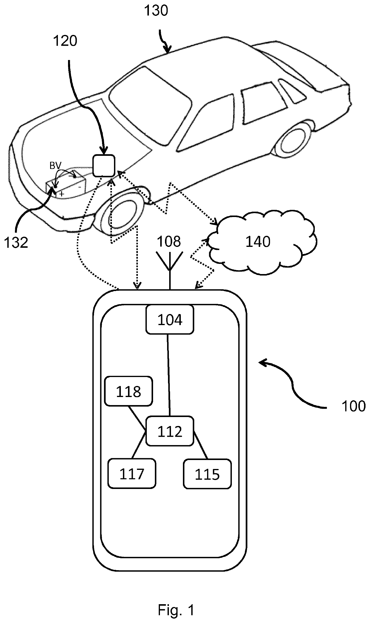
[0021]FIG. 1 schematically illustrates a battery monitoring unit 100 and an optional voltage sensor 120 according to an embodiment of the present invention. A craft 130 may be configured with a battery 132, e.g. serving as a power source of the craft. The battery monitoring unit 100 may be configured to monitor the battery 132 of the craft 130, e.g. the charging / discharging current and / or the capacity and / or a state-of-charge value. A craft 130 may be configured with a voltage sensor 120 comprised in and coupled to a battery 132 of the craft. Examples of crafts may be a vehicle, a caravan, an aircraft or a boat.

[0022]The voltage sensor 120 may be configured to measure a first plurality of voltage values of the battery 132 at multiple subsequent points in time, and / or send the first plurality of voltage values to the battery monitoring unit 100, e.g. via wired or wireless communication, such as Bluetooth, WiFi etc. In an example, the voltage sensor 120 comprises sensor means arranged...


PUM


Abstract

The disclosure relates to a method performed by a battery monitoring unit configured for estimating a battery discharging current of a battery comprising the steps obtaining a state-of-charge value indicative of a ratio between a current capacity and a maximum capacity of the battery, obtaining sensor data indicative of a first plurality of battery voltage values obtained at multiple subsequent points in time, determining a first voltage trend over time of the first plurality of battery voltage values, estimating a battery discharging current of the battery based on a relation, where the relation is dependent on the first voltage trend over time and the state-of-charge value.

Description

TECHNICAL FIELD[0001]The present invention relates to battery monitoring unit configured for estimating a battery discharging current of a battery. The invention further relates to a corresponding method, computer program, computer program product and carrier.BACKGROUND[0002]A battery is often used in a craft, such as a vehicle, caravan or a boat for various purposes. The conventional use of a battery, e.g. as a starter battery in a car, includes to the largest extent a charging phase where the battery receives a charging current and an idle phase where the battery delivers no or a very low discharge current. However, today a craft battery is often used also in a way that the battery is delivering a discharge current during longer periods of time.[0003]The capacity to deliver a discharge current from the battery may be given as a current capacity, e.g. in Ampere hours, and a maximum capacity corresponding to when the battery is fully charged. To keep track of the current capacity of...

Claims


Application Information

Patent Timeline
Patent Type & Authority Patents(United States)
IPC IPC(8): G01R31/367G01R31/3835G01R31/371
CPCG01R31/367G01R31/371G01R31/3835H01M2220/20
Inventor ANDERSSON, HELGE
Owner CTEK SWEDEN
Why Eureka
Try Eureka