Fluid dispenser with wake up sensor
- Summary
- Abstract
- Description
- Claims
- Application Information
AI Technical Summary
Problems solved by technology
Method used
Image

Examples
Example
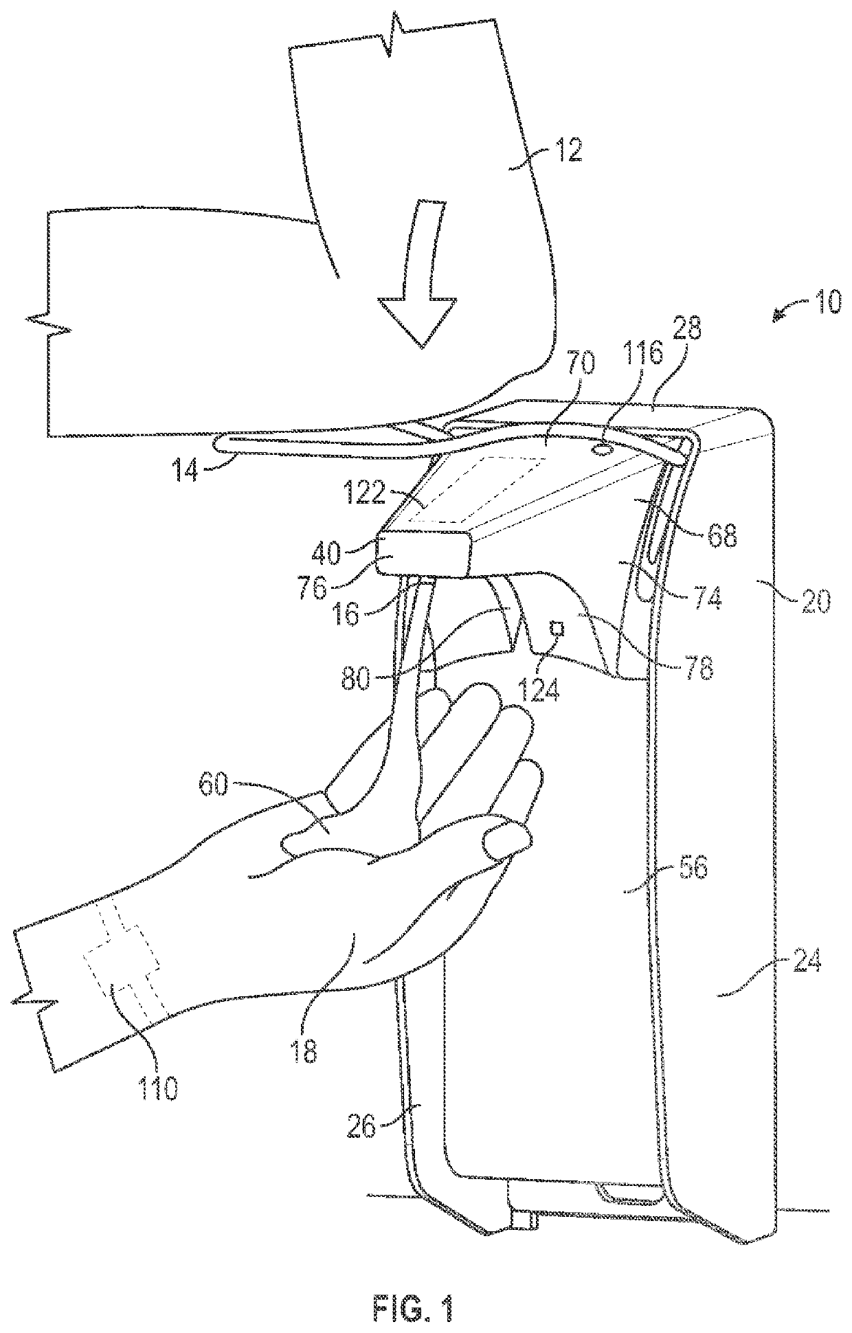
[0141]FIGS. 1 to 3 show a fluid dispenser 10 in accordance with a first embodiment of the present invention. The fluid dispenser 10 has a construction generally similar to that shown and described in U.S. Pat. No. 7,748,573 to Anhuf et al., issued Jul. 6, 2010, which is incorporated herein by reference.
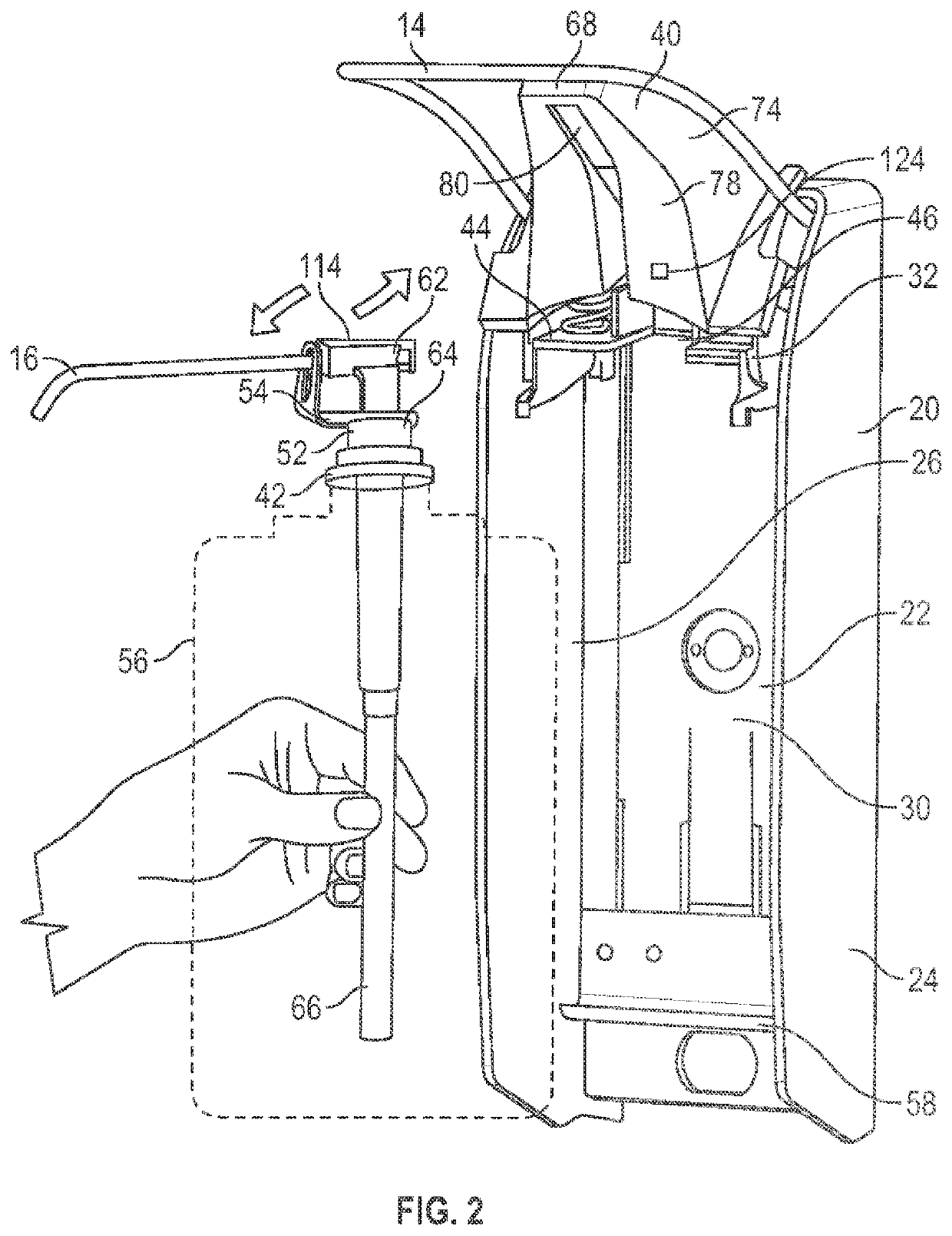
[0142]The fluid dispenser 10 is adapted to be secured to a wall, not shown, and is adapted for manual activation as shown in FIG. 1 as by a user using one arm 12 to urge a lever 14 downwardly so as to dispense fluid 60 from a nozzle 16 onto the hand 18 of the user's other arm.
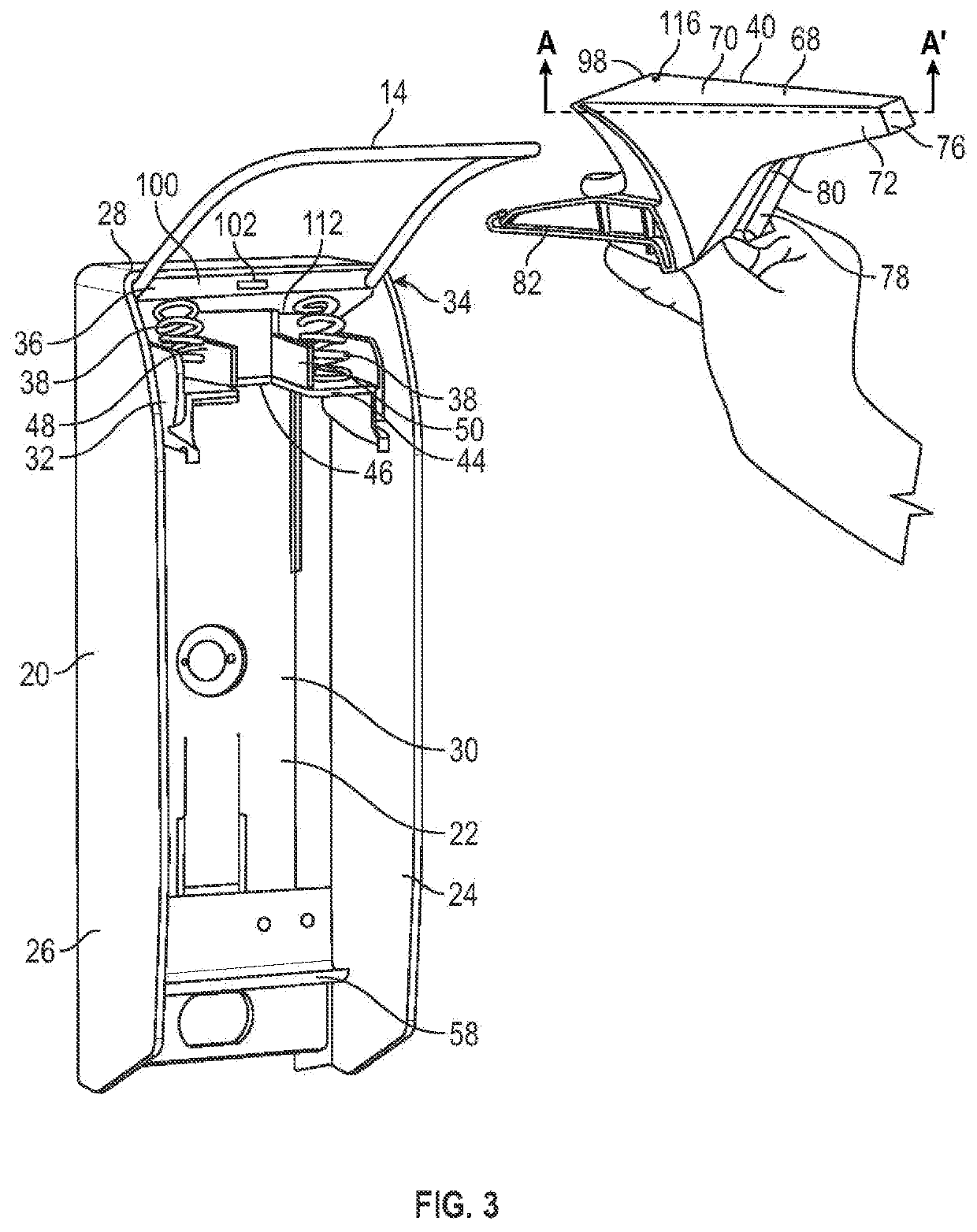
[0143]Referring to FIG. 3, the dispenser 10 includes a housing 20 having a back plate 22, spaced side walls 24 and 26, and a top wall 28 defining an interior 30 therebetween. A housing chassis / support member 32 is fixedly secured in the interior 30 of the housing 20 between the side walls 24 and 26 proximate the top wall 28. A lever mechanism 34 is pivotally mounted to the support member 32. The lever mechanism 3...
Example
[0190]Although not labelled on FIG. 16, the circuit board 84 of the second embodiment of the invention carries a battery 86, a microcontroller 88, a communication device 90, an activation sensor 92, a pump position sensor 94, and a bottle detector 96, each of which have the same structure and function as in the first embodiment of the invention shown in FIGS. 1 to 10 and described above. The activation sensor 92 and the pump position sensor 94 are positioned adjacent to a rear edge 98 of the top wall 70 of the nozzle shield 40, as in the first embodiment shown in FIGS. 1 to 10. The upper cover portion 130 and the lower cover portion 132 are preferably formed from a material that is transparent to infrared radiation, so that infrared radiation emitted by the light emitter 118 or the bottle detector 96, or detected by the light sensor 120 or the bottle detector 96, can pass through the upper cover portion 130 and the lower cover portion 132.
[0191]The relative position of the lever bri...
PUM
 Abstract
Description
Claims
Application Information
 - R&D Engineer
- R&D Manager
- IP Professional
- Industry Leading Data Capabilities
- Powerful AI technology
- Patent DNA Extraction
Browse by: Latest US Patents, China's latest patents, Technical Efficacy Thesaurus, Application Domain, Technology Topic.
© 2024 PatSnap. All rights reserved.Legal|Privacy policy|Modern Slavery Act Transparency Statement|Sitemap