Paver stone deck drain

a technology of draining and paver stone, applied in the field of draining, can solve the problems of unsafe conditions, aesthetic or structural damage, and lack of appropriate runoff area, and achieve the effect of preserving the aesthetics of the landscaped surfa

Active Publication Date: 2022-08-16
STETABON DEV
View PDF37 Cites 1 Cited by
  • Summary
  • Abstract
  • Description
  • Claims
  • Application Information

AI Technical Summary

Benefits of technology

[0008]Various aspects of the present disclosure are directed toward a drain configured to be incorporated into a surface formed from paver stones. The drain may be specifically adapted to reside beneath the paver stones and provide a drainage path between adjacent paver stones and into a drain pipe. In this regard, one or more paver stones may act as the lid or cover to the drain, thereby preserving the aesthetics of the landscaped surface.

Problems solved by technology

Consequently, water and other liquids may accumulate on the surface, which may result in slick, unsafe conditions.
Furthermore, if the water is not removed from the surface, the water may cause aesthetic or structural damage.
However, in other cases, the particular landscaped surface is situated such that an appropriate runoff area is not available.
In particular, drain covers constructed from dissimilar materials can be a safety hazard because the cover will generally have a different coefficient of friction compared to the surrounding landscaped surface.
A significant change in surface texture such as this increases the risk of a slip and fall accident as unsuspecting persons step from one surface having a high coefficient of friction to another having a lower coefficient of friction or visa-versa.
Moreover, the risk of an accident can be especially great when the cover is wet, as may be the case when children are playing near a swimming pool.
In addition to creating a potential safety hazard, drain covers constructed from dissimilar materials can also be less desirable for cosmetic reasons.
In many cases, a large amount of time and money is spent to make the landscaped surface look as aesthetically pleasing as possible.

Method used


Image

  • Paver stone deck drain
  • Paver stone deck drain
  • Paver stone deck drain

Examples


Embodiment Construction

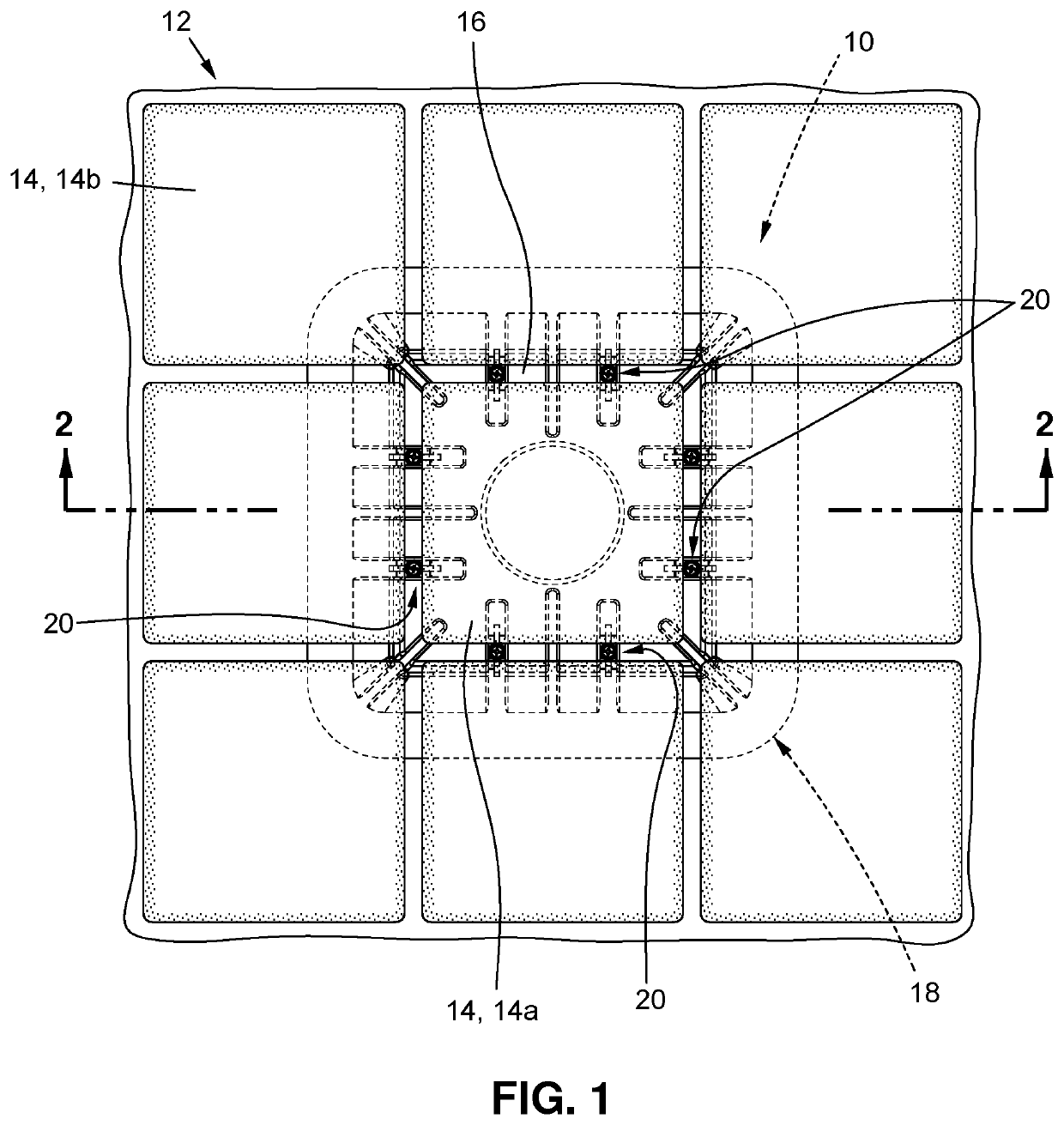
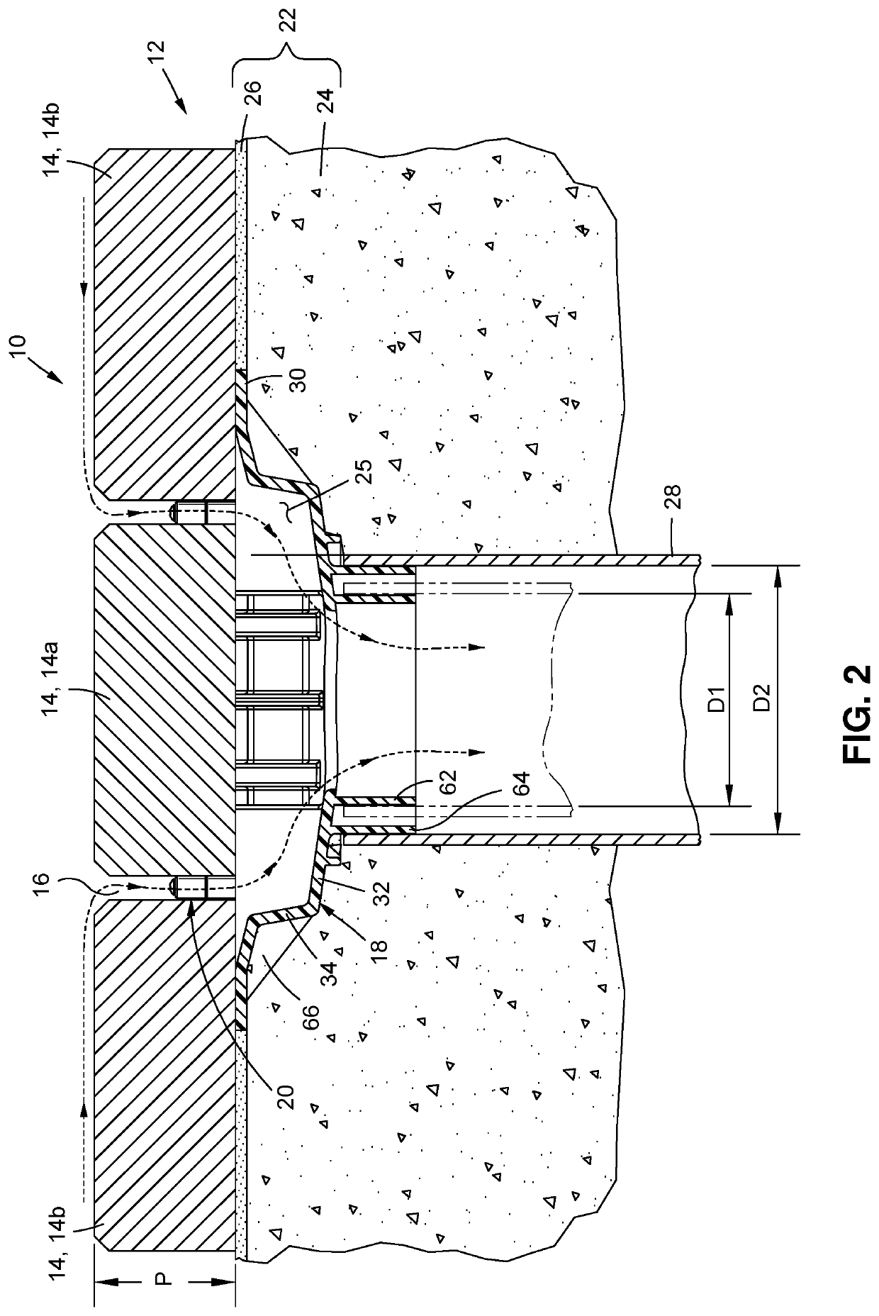
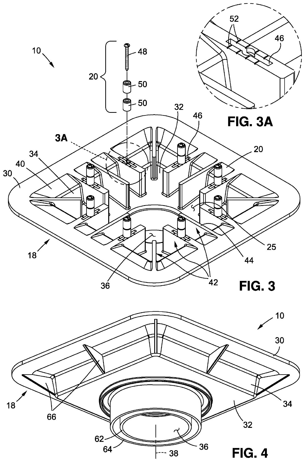
[0028]Referring now to the drawings, wherein the showings are for purposes of illustrating preferred aspects of the present disclosure, and are not for purposes of limiting the same, there is depicted a drain 10 for use in a landscaped surface 12 formed of paver stones 14. The drain 10 is configured to reside beneath an upper, exposed surface of the paver stones 14 to remain substantially hidden or concealed from view. Furthermore, the drain 10 is configured to allow for a paver stone 14a to be placed on top of the drain 10 to minimize the disruption of the layout of paver stones 14 in the landscaped surface 12. The drain 10 may create a small gap 16 around the paver stone 14a placed thereon to create a drainage pathway through the landscaped surface 12. The drain 10 may include a cavity under the paver stone 14a, in communication with the small gap 16, with the cavity being in communication with an underlying drain pipe. Accordingly, the drain 10 may provide an aesthetically pleasi...


PUM


Abstract

A drain is provided which may be used in a surface including a paver stone. The drain includes a body having an upper wall and a cavity extending from the upper wall. The body further includes a drain opening in fluid communication with the cavity. The body additionally includes a plurality of support members. Each support member at least partially extends into the cavity and includes a support surface, with the support surfaces of the plurality of support members being configured to collectively support a paver stone placed thereon. The drain additionally includes a plurality of retainers selectively engageable with the body to collectively define a paver zone sized to receive the paver stone. The body includes a drainage pathway from a location outside of the paver zone, through the cavity and to the drain opening.

Description

CROSS-REFERENCE TO RELATED APPLICATIONS[0001]Not ApplicableSTATEMENT RE: FEDERALLY SPONSORED RESEARCH / DEVELOPMENT[0002]Not ApplicableBACKGROUND1. Technical Field[0003]The present disclosure relates generally to a drain for use in landscaping applications, and more specifically to a drain that may be incorporated into a surface formed from paver stone.2. Description of the Related Art[0004]Many residential and commercial buildings include decorative or landscaped surfaces, such as decks, patios, porches, garages, etc. Such surfaces are commonly located outside and exposed to precipitation, or located adjacent a pool, sprinkler, or water feature. Consequently, water and other liquids may accumulate on the surface, which may result in slick, unsafe conditions. Furthermore, if the water is not removed from the surface, the water may cause aesthetic or structural damage. Therefore, many surfaces are oftentimes graded to induce runoff in a predisposed direction. In some cases, the liquid ...

Claims


Application Information

Patent Timeline
Patent Type & Authority Patents(United States)
IPC IPC(8): E01C11/00E01C11/22
CPCE01C11/227E01C2201/20
Inventor STETSON, MICHAEL A.
Owner STETABON DEV
Why Eureka
Try Eureka