Imagaing optical system, projection display device, and imaging apparatus

a projection display device and optical system technology, applied in the field of imaging optical systems, can solve the problems of degrading the beam performance, not being able to achieve temperature compensation and optical performance, and not being able to use design in different specifications

Active Publication Date: 2022-08-16
FUJIFILM CORP
View PDF3 Cites 0 Cited by
  • Summary
  • Abstract
  • Description
  • Claims
  • Application Information

AI Technical Summary

Benefits of technology

[0009]In recent years, with the increase in the number of pixels of an image display element mounted on the optical device, the resolution of the imaging optical system is also required to be increased. Therefore, the influence of the temperature drift is easily noticeable, and high-precision temperature compensation is required.
[0029]According to the embodiment of the present invention, it is possible to provide an imaging optical system capable of achieving high optical performance and high-precision temperature compensation, a projection display device comprising the imaging optical system, and an imaging apparatus comprising the imaging optical system.

Problems solved by technology

For finely correcting the variation in the focus position due to the temperature, suppressing the lens shape is required, but in a case of changing the lens shape for temperature compensation, aberration performance is degraded, it is not possible to achieve temperature compensation and optical performance at the same time.
In a design of JP2016-142883A as an example, it is possible to perform temperature compensation, but the design cannot be employed in different specifications because it is difficult to achieve temperature compensation and good optical performance at the same time due to the above-mentioned problem.

Method used


Image

  • Imagaing optical system, projection display device, and imaging apparatus
  • Imagaing optical system, projection display device, and imaging apparatus
  • Imagaing optical system, projection display device, and imaging apparatus

Examples


example 1

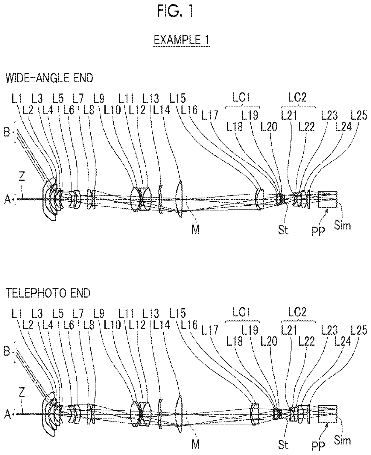
[0058]FIG. 1 is a cross-sectional view illustrating a configuration of the imaging optical system of Example 1. Since the method illustrated in FIG. 1 has been described above, some repeated descriptions will be omitted here. Further, the illustration method is basically the same in Examples 2 to 4.

[0059]The imaging optical system of Example 1 has a zooming function and consists of twenty five lenses L1 to L25 in order from the magnification side to the reduction side along the optical axis Z, and is a relay type imaging optical system in which an intermediate image M is formed between L14 and L15. In addition, the intermediate image M is schematically illustrated in FIG. 1 and does not show an actual shape.

[0060]The imaging optical system of Example 1 includes two lens pairs, the first lens pair LC1 consisting of lenses L18 and L19, and the second lens pair LC2 consisting of lenses L21 and L22.

[0061]Also, a first moving lens group is composed of two lenses L15 and L16, a second mov...


PUM


Abstract

An imaging optical system includes a plurality of lenses, and the plurality of lenses includes a lens pair consisting of two lenses arranged near each other, in which radii of curvature of two surfaces arranged near each other is close to each other, and which satisfies predetermined conditional expressions.

Description

CROSS REFERENCE TO RELATED APPLICATIONS[0001]The present application claims priority under 35 U.S.C. § 119 to Japanese Patent Application No. 2018-179427 filed on Sep. 25, 2018, and Japanese Patent Application No. 2019-021043 filed on Feb. 7, 2019. The above applications are hereby expressly incorporated by reference, in its entirety, into the present application.BACKGROUND OF THE INVENTION1. Field of the Invention[0002]The present disclosure relates to an imaging optical system, a projection display device, and an imaging apparatus.2. Description of the Related Art[0003]An imaging optical system suitable for a digital camera or a projector is disclosed, for example, in JP2016-142883A.SUMMARY OF THE INVENTION[0004]In a case where temperature change occurs in an imaging optical system, a focus position may change as such, which is what is called “temperature drift.” The degree of the temperature drift of the imaging optical system is determined by a material and shape of a lens, the ...

Claims


Application Information

Patent Timeline
Patent Type & Authority Patents(United States)
IPC IPC(8): G02B15/14H04N5/225G03B17/14G02B27/18G02B19/00
CPCG02B15/142G03B17/14H04N5/2254G02B19/0004G02B27/18G02B13/00G02B15/14G02B13/18G02B27/0025H04N23/55
Inventor NAGATOSHI, YUKIKO
Owner FUJIFILM CORP
Why Eureka
Try Eureka