
Large field of view see through head mounted display having magnified curved intermediate image

a head mounted display and large field of view technology, applied in the field of optical structures, can solve the problems of limited size of eye boxes, undesirable or even unacceptable form factors, and large volume of refractive/reflective head mounted display devices, and achieve the effects of convenient implementation, convenient compact form factors, and convenient implementation

Active Publication Date: 2022-09-06
HONG KONG APPLIED SCI & TECH RES INST
View PDF23 Cites 0 Cited by
  • Summary
  • Abstract
  • Description
  • Claims
  • Application Information

AI Technical Summary

Benefits of technology

[0006]Optical structures comprising a catadioptric optical configuration in accordance with embodiments of the invention facilitate HMD device implementations that are inexpensive, lightweight, and compact, yet provide a large FOV. Such optical structures are particularly well suited for use in large FOV optical see through (OST) HMDs. Large FOV OST-HMDs implementing optical structures in accordance with concepts of the present invention may, for example, be utilized in heads-up-display, virtual reality (VR), augmented reality (AR), Internet of thins (IoT) applications, etc. Large FOV OST-HMDs comprising optical structures of embodiments of the invention may be utilized in implementing virtual imaging head mounted displays used for wearable personal display applications such as AR / VR. For example, a compact large FOV OST-HMD implemented using an optical structure in accordance with concepts of the present invention may be utilized by AR / VR wearable product manufacturers to create next generation low cost AR / VR smart glasses with large a FOV see-through display and having a small form factor. Large FOV OST-HMD implementations using optical structures comprising a catadioptric optical configuration of embodiments may, for example, lower the wearable smart AR / VR glasses products entry barrier, allowing more companies to enter the AR / VR wearable market.
[0008]Optical structures comprising a catadioptric optical configuration in accordance with embodiments of the invention facilitate implementations in which imaging and illumination share a same optical axis. For example, a light source (e.g., LED array, electro luminescent panel, etc.) may be disposed on the optical axis shared by the image display to provide illumination thereto. Such implementations are particularly well suited to provide illumination of otherwise unilluminated displays (e.g., LCoS displays) or otherwise under illuminated displays, while facilitating a compact form factor.
[0009]Optical structures comprising a catadioptric optical configuration in accordance with embodiments of the invention facilitate implementations in which virtual display and eye sensing share a same optical axis. For example, an imaging sensor (e.g., infrared (IR) sensor) may be disposed on the optical axis shared by the virtual image for eye tracking (e.g., eye movement detection, point of focus tracking, iris capturing, etc.). Such implementations are particularly well suited to enable advanced features associated with eye tracking, while facilitating a compact form factor.

Problems solved by technology

Each of these head-mounted display configurations has drawbacks associated therewith.
For example, conventional refractive / reflective head-mounted display devices are relatively bulky, thus presenting an often undesirable or even unacceptable form factor for many applications due to the resulting size and styling constraints.
Moreover, conventional refractive / reflective optics produce a resulting eye box of limited size and the combiner optic is typically relatively thick.
Conventional diffractive head-mounted display devices provide relatively limited field of view (FOV) capabilities.
For a large FOV (i.e., >50°) head-mounted display implementation, the optical system is bulky such as due to the need for a large image source size (e.g., 3.5 inch˜0.7 inch) and / or the bulky optical structure required.
The coherent fiber optic cable used in conventional laser writer HMD configurations is very expensive.
From the foregoing it can be seen that head-mounted display configurations that provide for inexpensive, lightweight, and compact head-mounted display devices having a broad FOV in combination with other desirable attributes are problematic for conventional implementations.

Method used


Image

  • Large field of view see through head mounted display having magnified curved intermediate image
  • Large field of view see through head mounted display having magnified curved intermediate image
  • Large field of view see through head mounted display having magnified curved intermediate image

Examples


Embodiment Construction

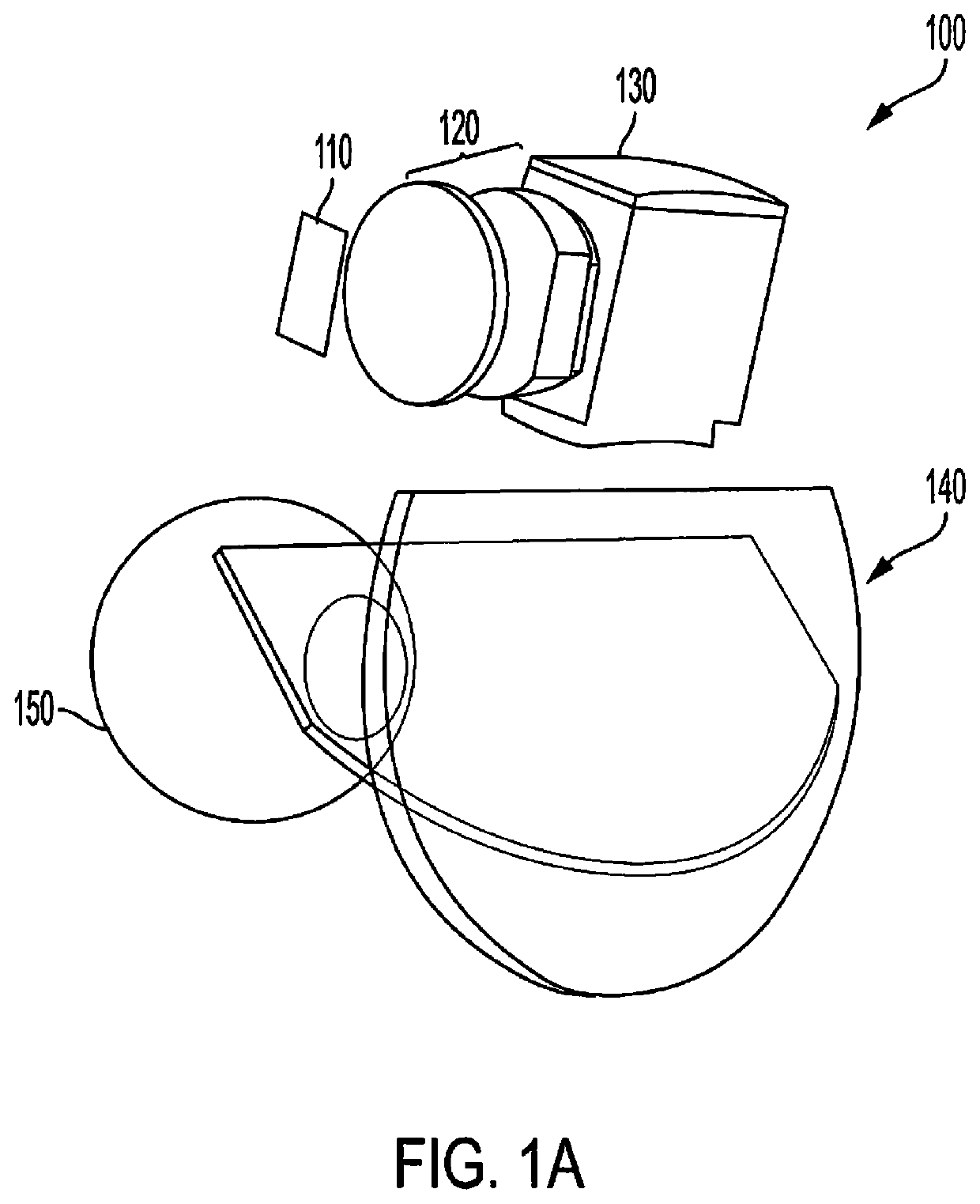
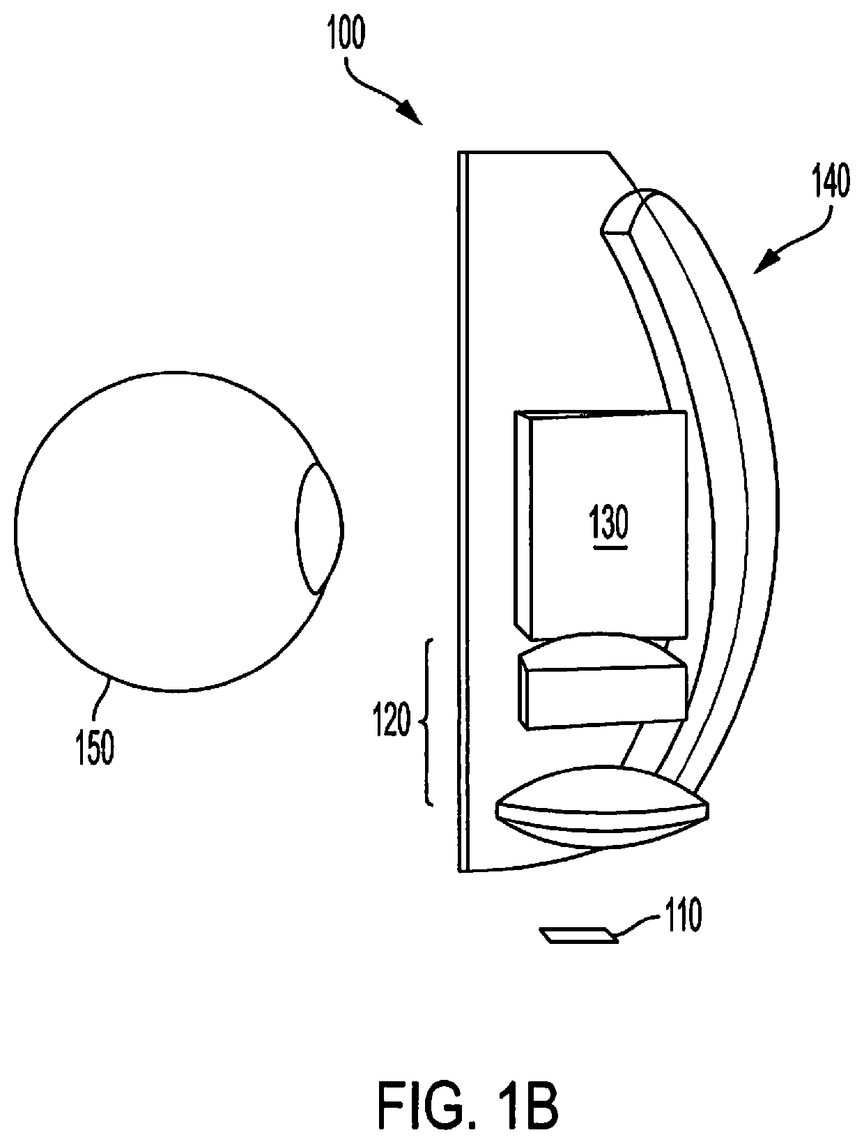
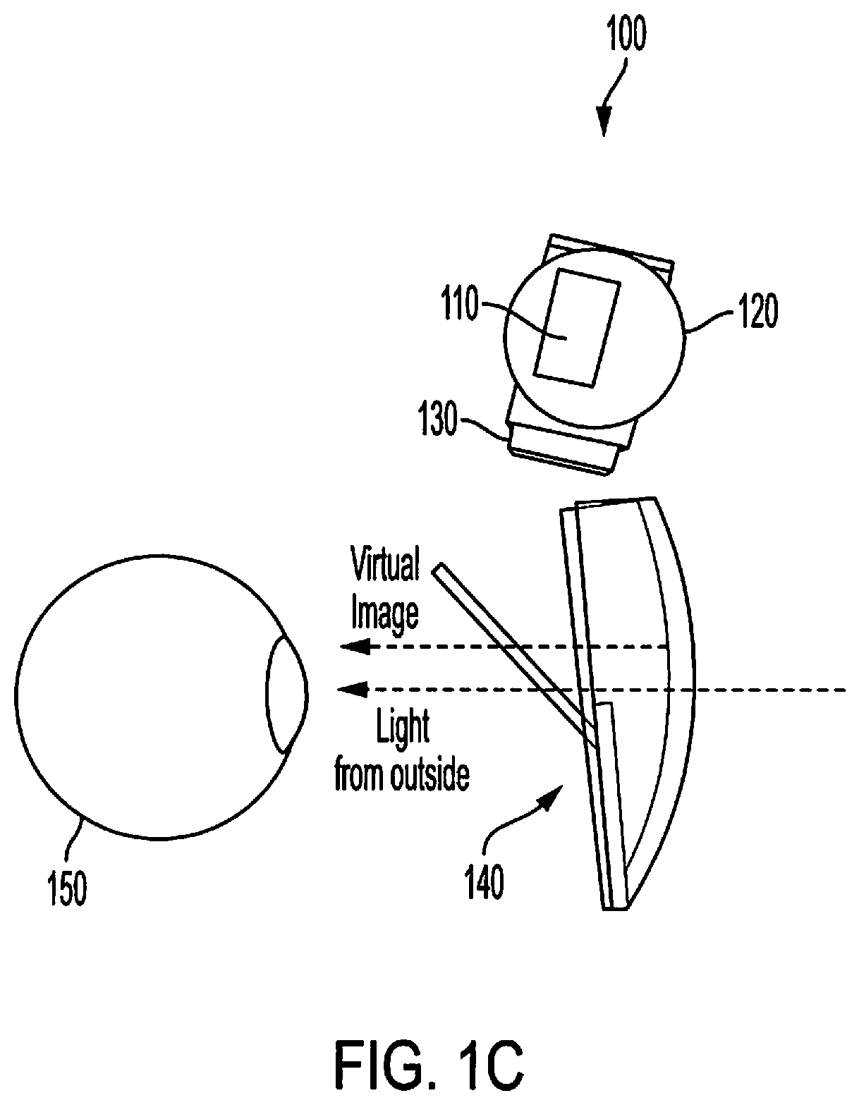
[0017]FIGS. 1A-1C show an optical structure comprising a catadioptric optical configuration in accordance with embodiments of the invention. In particular, FIG. 1A shows an isometric view of optical structure 100, while FIG. 1B shows a top view of optical structure 100 and FIG. 1C shows a side view of optical structure 100. Viewer's eye 150 is shown in FIGS. 1A-1C to illustrate the eye-box (i.e., the volume of space within which an effectively viewable image is formed) position with respect to optical structure 100.

[0018]Optical structure 100 of the illustrated embodiment comprise a catadioptric (hybrid refractive / reflective) optical configuration. Optical structure 100 comprises display 110 for supplying an image presented to the viewer as a virtual image through operation of the catadioptric optical configuration. Display 110 may, for example, display images generated from data provided by a processor-based system (not shown) connected thereto. Such processor-based systems may inc...


PUM


Abstract

Systems and methods providing optical structures providing a large field of view (FOV) for personal portable displays are described. An optical structure of embodiments comprises a catadioptric optical configuration configured to produce a magnified curved intermediate image, wherein the magnified curved intermediate image is furthered magnified with proper reflection angle and transmitted to viewer's eye. The catadioptric optical configuration may comprise two curved mirrors and a polarization prism. Optical structures comprising such catadioptric optical configurations may utilize relatively small sized image sources to produce a large FOV. Such optical structures are well suited for use in large FOV optical see through (OST) head-mounted displays (HMDs).

Description

TECHNICAL FIELD[0001]The present invention relates generally to optical structures and, more particularly, to optical structure designs providing large fields of view, such as for use in large field of view optical see through head mounted displays.BACKGROUND OF THE INVENTION[0002]Display technology and electronics have progressed to the point that display systems have been introduced in a variety of form factors which have traditionally been impossible or impractical. For example, various forms of head-mounted displays have been developed to provide display of images and information to a viewer in real-time environments. Head-mounted display devices may, for example, be found in today's military, commercial, and consumer markets.[0003]A head-mounted display is a display device that is worn on a viewer's head that has either one or two small displays (e.g., liquid crystal display (LCD) or light emitting diode (LED) display panel) located in front of each of the viewer's eyes. An opt...

Claims


Application Information

Patent Timeline
Patent Type & Authority Patents(United States)
IPC IPC(8): G02B27/00G02B27/01G02B27/28
CPCG02B27/0172G02B27/0093G02B27/283G02B2027/013G02B2027/0123G02B2027/0138
Inventor LIU, DEHUAWONG, CHUN YIPCHAN, KIN LUNG
Owner HONG KONG APPLIED SCI & TECH RES INST
Learn More