Supercharge Your Innovation With Domain-Expert AI Agents!

Reinforced wheel for a vehicle

a technology for reinforced wheels and vehicles, applied in the direction of spoked wheels, transportation and packaging, rolling resistance optimization, etc., can solve the problems of high overall weight of wheels, and achieve the effect of good reinforcement of spokes and pronounced reinforcement

Active Publication Date: 2022-10-11
MUBEA CARBO TECH GMBH
View PDF17 Cites 0 Cited by
  • Summary
  • Abstract
  • Description
  • Claims
  • Application Information

AI Technical Summary

Benefits of technology

[0012]The at least one spoke comprises a reinforcing member extending along the inner surface of the spoke. In a preferred variation, the at least one reinforcing member protrudes from the inner surface of the spoke into the cavity extending above the inner surface of the spoke separating the inner surface in zones, as will be described in more detail hereinafter. Alternatively or in addition, the reinforcing member may protrude at least partially from the inner surface into the spoke and / or may be arranged in a respective furrow of the outer wall, which can improve the anchoring. Furthermore, it may facilitate the mounting of the reinforcing member. Advantageously, the at least one reinforcing member is at least partially made of fiber reinforced composite material. The reinforcing member is normally attached to the outer wall, respectively the wheel center, by glue, such as e.g. the resin of the fiber reinforced material. Good results in terms of stability and stiffness of the reinforcing member can be achieved, if the reinforcing member is at least partially made from unidirectional fibers which can be at least partially embedded in the outer wall of the spoke. The outer wall is preferably made from fiber reinforced composite material. Good results can be achieved when the fiber reinforced material of the outer wall consists at least partially from several layers having different fiber directions with respect to the longitudinal direction of the spoke. Depending on the field of application, the outer wall, respectively the spokes, can also be made from metal. The reinforcing member may be a separate element interconnected to the at least one spoke and / or it can be made as an integral part of the spoke, i.e. it is made from the same material. If the wheel center is made of fiber reinforced composite material, the reinforcement member may alternatively also be manufactured in one piece together with the wheel center.
[0015]Depending on the application and the design of the wheel, the at least one rib may further have different shapes. The at least one rib may e.g. be ring or spiral or U-shaped. A good reinforcement of the spoke may be achieved by a ring or spiral-shaped rib, by orienting the rib around a middle axis (extending from the hub towards the rim) of the at least one spoke. A ring shaped rib may be oriented in a first plane essentially perpendicular to said middle axis (hence extending in the transverse direction). For a more pronounced reinforcement effect, multiple ring-shaped ribs can be provided. Preferably, these multiple ribs are arranged at least partially parallel to each other. Using a U-shaped rib may be advantageous, if the rib is arranged in the longitudinal direction with the cavity having an opening. The bottom of the U-shaped rib, connecting the two legs of the U, is then placed at the inner end of the cavity (opposite of the opening), such that the ends of the two legs are directed towards the opening of the cavity. Furthermore, if the reinforcing member extends towards the rim, it is advantageous if the ends of the reinforcing member follow the shape of the rim, such that additional support for the interconnection between the rim and the wheel center is given. The U-shaped rib is hereby preferably oriented in a second plane, defined by the middle axis of the at least one spoke and a rotation axis of the wheel or arranged rotated to that by 90 degrees (around the middle axis).

Problems solved by technology

Therefore, the wall thickness has to be carefully designed and locally thickened according to the specific load cases, which again leads to a higher overall weight of the wheel.

Method used


Image

  • Reinforced wheel for a vehicle
  • Reinforced wheel for a vehicle
  • Reinforced wheel for a vehicle

Examples


Embodiment Construction

[0029]Reference will now be made in detail to certain embodiments, examples of which are illustrated in the accompanying drawings, in which some, but not all features are shown. Indeed, embodiments disclosed herein may be embodied in many different forms and should not be understood as limited to the embodiments set forth herein; rather, these embodiments are provided so that this disclosure will satisfy applicable legal requirements. Whenever possible, like reference numbers will be used to refer to like components or parts.

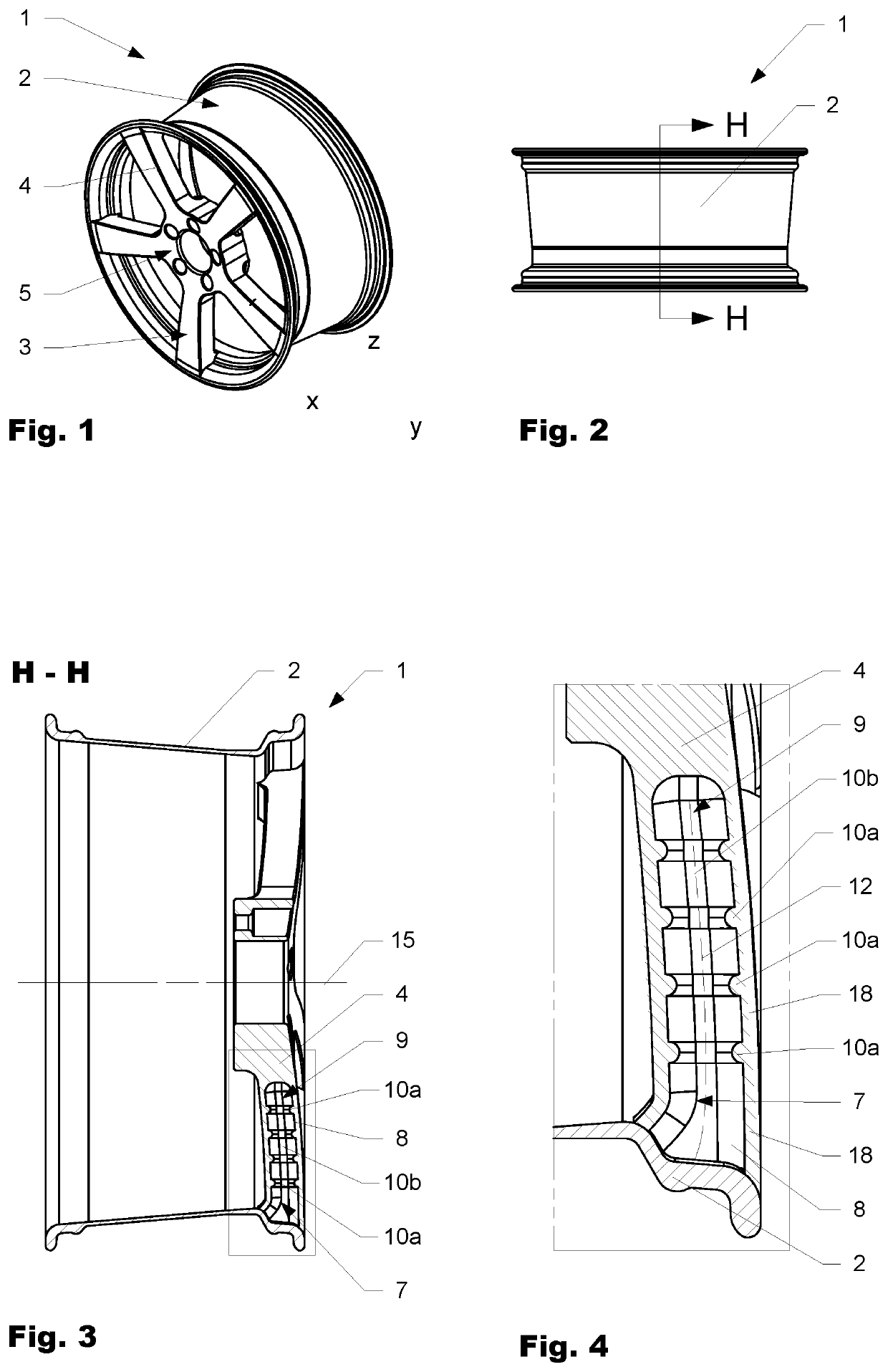
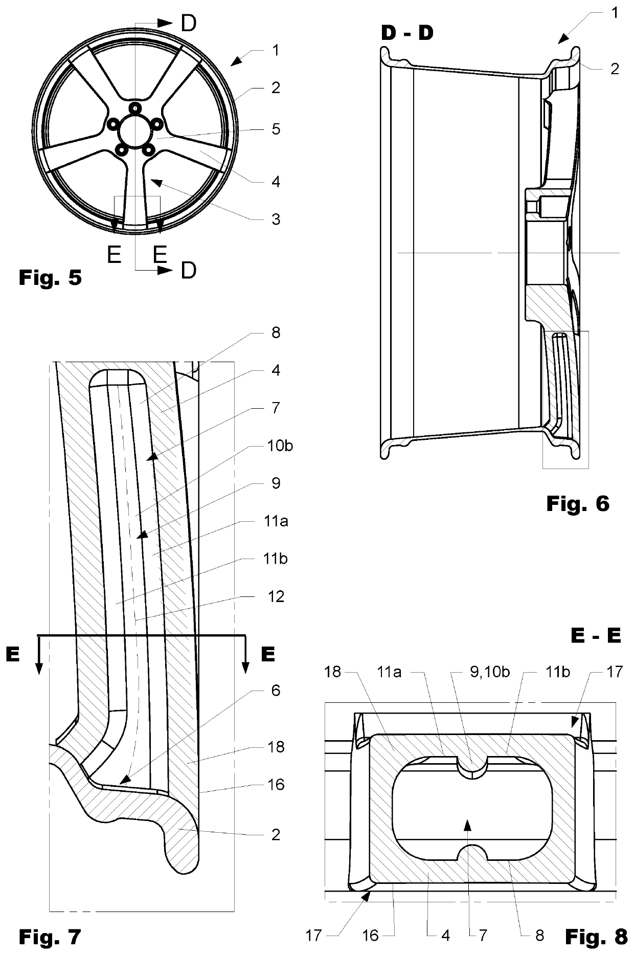
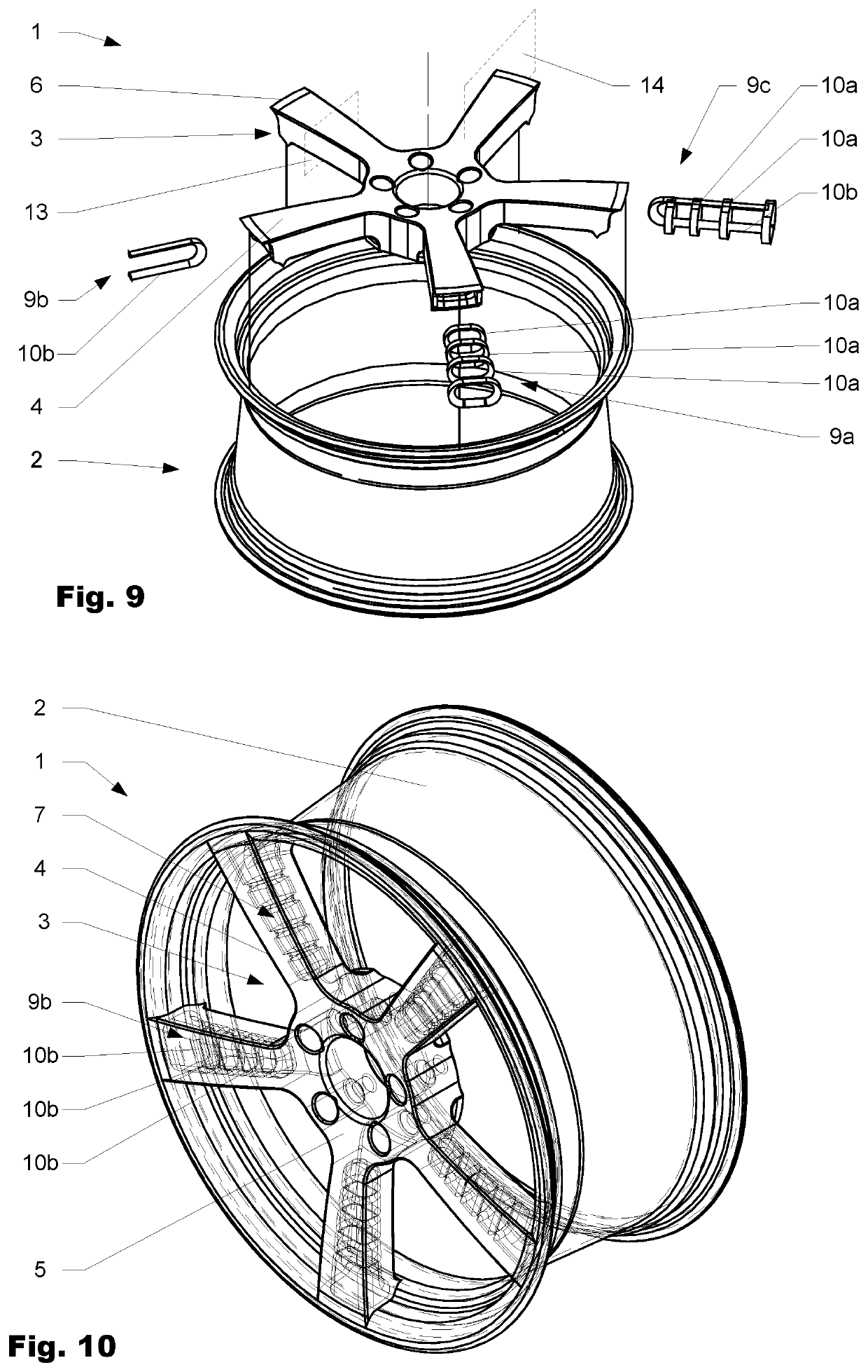
[0030]FIG. 1 to FIG. 4 show a first variation of the wheel 1 according to the disclosure. The wheel 1 comprises a rim 2 and a wheel center 3. The wheel center 3 further comprises several spokes 4 extending radially outwards from a wheel hub 5 towards the rim 2. FIG. 3 and FIG. 4 hereby offer a cross-sectional view into one spoke 4 extending in the longitudinal direction of the spoke 4 having a cavity 7. The cavity 7 is extending in the longitudinal direction and...


PUM

PropertyMeasurementUnit
rotation axisaaaaaaaaaa
thicknessaaaaaaaaaa
total weightaaaaaaaaaa

Abstract

Wheel comprising a rim and a wheel center wherein the wheel center comprises several spokes extending in a longitudinal direction from a wheel hub to the rim. At least one spoke comprises an outer wall surrounding a cavity extending in the longitudinal direction of the at least one spoke. The cavity is delimited from the outer wall by an inner surface. The at least one spoke further comprises a reinforcing member extending along the inner surface.

Description

CROSS-REFERENCE TO RELATED APPLICATIONS[0001]This application claims the benefit of the filing date of international PCT Application No. PCT / EP2018 / 076387, filed on Sep. 28, 2018, that in turn claims priority to Swiss Patent Application No. CH 01193 / 17, filed on Sep. 29, 2017, the contents of which are hereby incorporated by reference in their entirety.FIELD OF THE INVENTION[0002]The invention lies in the field of wheels made at least partially out of fiber reinforced material for passenger vehicles such as cars, motorcycles, etc.BACKGROUND OF THE INVENTION[0003]Wheels for vehicles must meet a comprehensive list of requirements, including specific dimensions, minimum mechanical competence, maximum total weight, specified mass distribution, durability and visual appearance. Light vehicle wheels are desirable to improve the driving quality and performance as well as to keep the overall vehicle weight light. At the same time, safety regulations exist to ensure sufficient durability, es...

Claims


Application Information

Patent Timeline
Patent Type & Authority Patents(United States)
IPC IPC(8): B60B1/12B60B5/02B60B1/14
CPCB60B1/12B60B5/02B60B1/14B60B2360/341B60B3/10B60B2900/111Y02T10/86
Inventor RENNER, CHRISTOPH
Owner MUBEA CARBO TECH GMBH
Features
  • R&D
  • Intellectual Property
  • Life Sciences
  • Materials
  • Tech Scout
  • Unparalleled Data Quality
  • Higher Quality Content
  • 60% Fewer Hallucinations
Learn More