
Hinge pin remover tool

a technology of remover and hinge pin, which is applied in the direction of manufacturing tools, door/window fittings, construction, etc., can solve the problems of cumbersomeness, ineffectiveness, and high cost, and achieves the effects of reducing labor intensity, avoiding damage to hinge pins, and avoiding damage to hinge parts

Active Publication Date: 2022-11-01
MUSTOE TRACY
View PDF4 Cites 0 Cited by
  • Summary
  • Abstract
  • Description
  • Claims
  • Application Information

AI Technical Summary

Benefits of technology

The present invention is a tool to remove a hinge pin from a door hinge assembly. The tool includes a geared wheel with teeth that engage with the hinge pin, and a push rod to push the hinge pin out as the geared wheel rotates. There is also a forked clip to pull the hinge pin out as the geared wheel rotates. The tool's design allows for easy and efficient removal of hinge pins without causing damage to the door.

Problems solved by technology

This method can unfortunately cause damage to the hinge pin, the hinge assembly, the door, the door frame, and the surrounding walls.
There are prior art hinge pin removers, but they tend to be cumbersome, expensive, impractical and ineffective.

Method used


Image

  • Hinge pin remover tool
  • Hinge pin remover tool
  • Hinge pin remover tool

Examples


Embodiment Construction

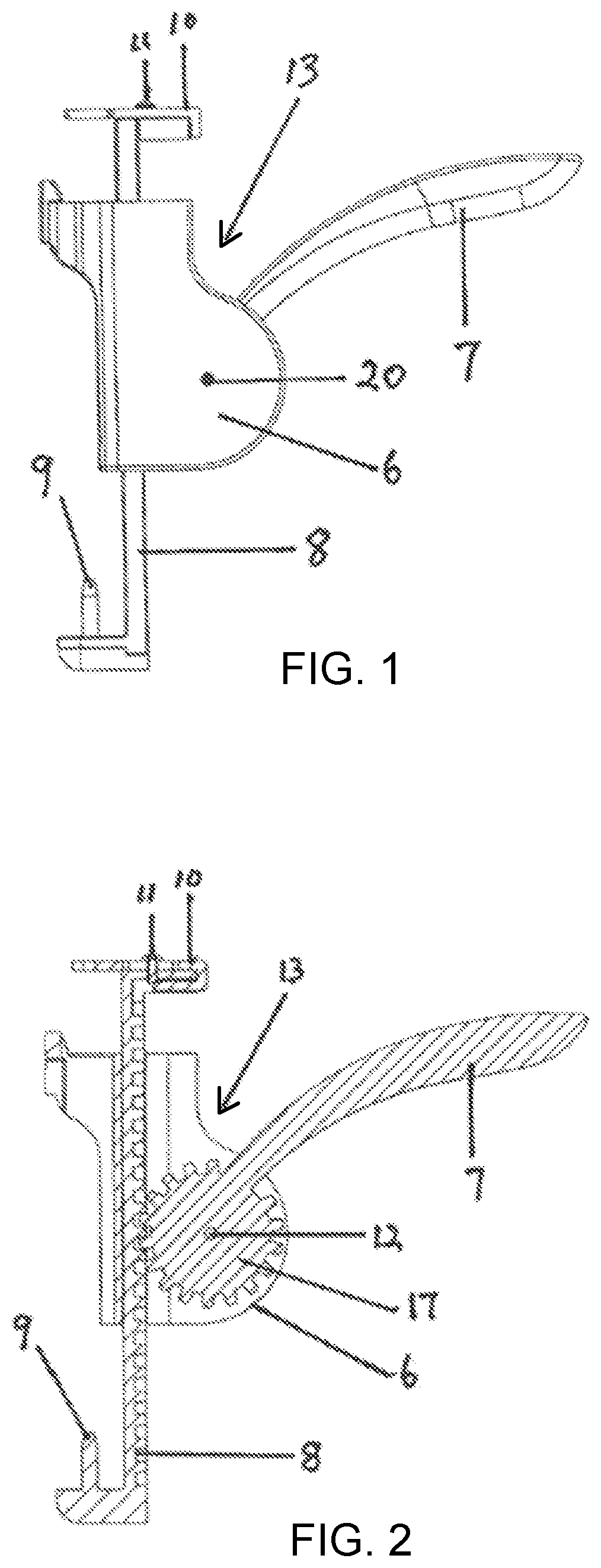
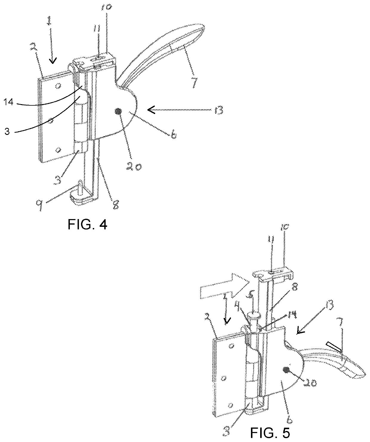
[0011]FIGS. 4-5 show the utilization of hinge pin remover 13. Hinge pin remover 13 is utilized to remove hinge pin 5 from hinge assembly 1. Initial downward motion on lever 7 causes lower push rod 9 (FIG. 4) to push hinge pin 5 upward. Later downward motion on lever 7 then causes forked clip 10 to pull hinge pin 5 upward to fully remove it from hinge assembly 1 (FIGS. 4-7).

[0012]Components of Hinge Remover

[0013]FIGS. 1 and 2 show a side view of hinge remover 13. FIGS. 3A-3F show front and side views of individual components of hinge remover 13.

[0014]Forked Clip

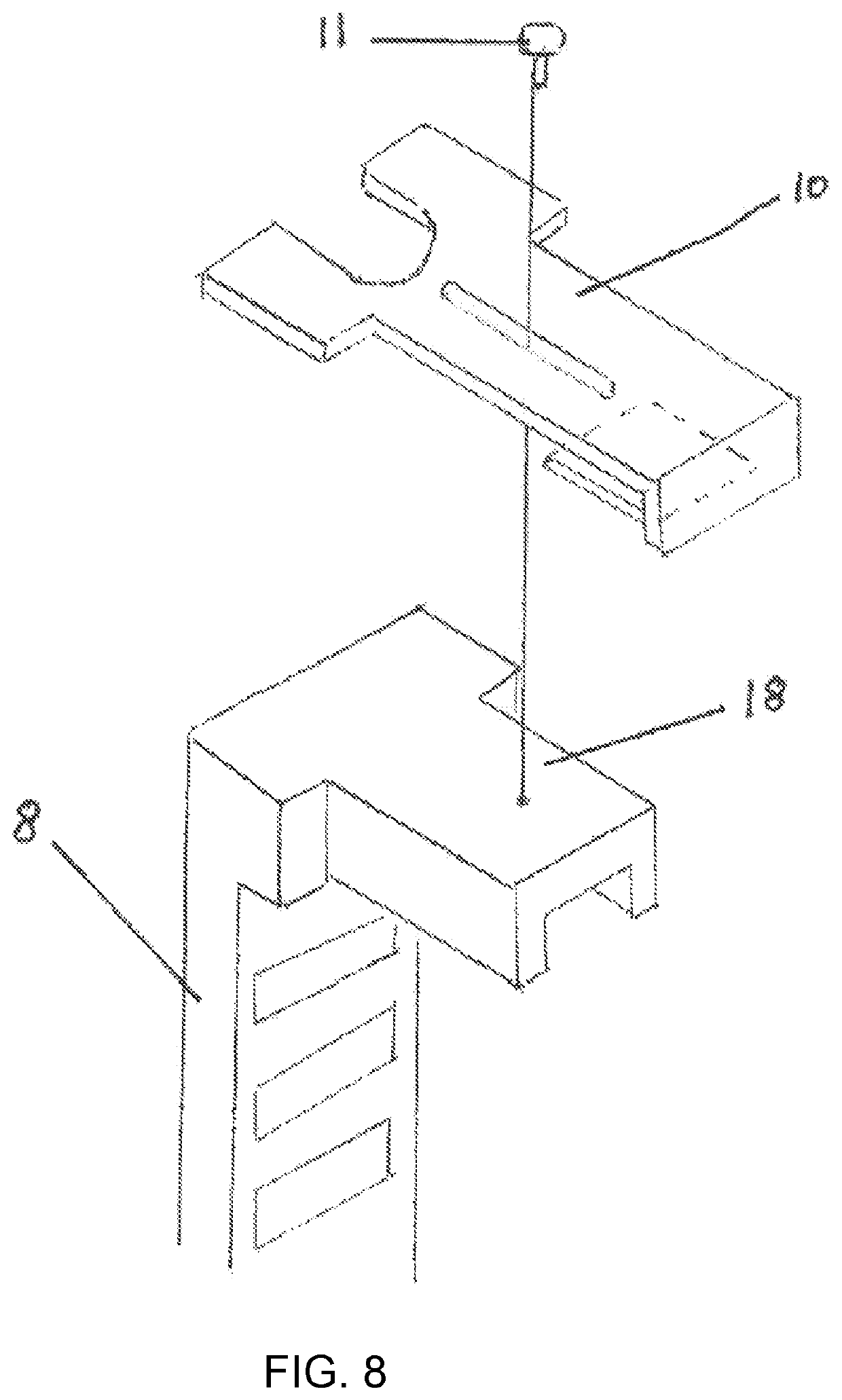
[0015]Forked clip 10 is sliding connected to upper arm 18 of geared shaft 8 (FIGS. 1, 2, 3D, and 8). Forked clip 10 preferably includes retainer pin 11 (FIGS. 1, 2, and 3F) that is utilized to prevent forked clip 10 from sliding off upper arm 18.

[0016]Geared Shaft

[0017]Geared shaft 8 extends downward through body 6 (FIGS. 1 and 2). Geared shaft 8 includes rigidly attached upper arm 18 at its upper end and rigidly attached lowe...


PUM

PropertyMeasurementUnit
vertical heightaaaaaaaaaa
vertical movementaaaaaaaaaa
lengthaaaaaaaaaa

Abstract

A hinge pin remover for removing a hinge pin from a door hinge assembly. A geared wheel is rotatably connected to a hinge pin remover body. The geared wheel includes a plurality of geared wheel teeth. A handle is rigidly connected to the geared wheel. A geared shaft extends through the remover body. The geared shaft includes a plurality of geared shaft teeth. The geared shaft teeth are engaged with the geared wheel teeth. A lower push rod is connected to the geared shaft and is for pushing the hinge pin as the geared wheel is rotated. A forked clip is slidingly connected to the geared shaft and is for pulling the hinge pin as the geared wheel is rotated.

Description

[0001]The present invention relates to hand tools, and in particular to hand tools for removing door hinge pins. This application claims the benefit of U.S. Provisional Application No. 62 / 389,481, filed on Mar. 1, 2016, all of which is incorporated by reference herein.BACKGROUND OF THE INVENTION[0002]A door hinge (also known as a door hinge assembly) is very common in society. A typical door hinge assembly includes a door hinge pin that extends through the door hinge assembly. The hinge assembly is connected between the door and the door frame and allows for the opening and closing of the door.[0003]Often it is necessary to remove the door for maintenance, repairs, or other reasons. To remove the door from the door frame, the user must first remove the hinge pin. The most common way to do this is to use a hammer and a screwdriver. The user typically places the screwdriver against the bottom of the hinge pin with and then taps the screwdriver with the hammer to push the pin out. This...

Claims


Application Information

Patent Timeline
Patent Type & Authority Patents(United States)
IPC IPC(8): B25B27/04E05D7/10
CPCB25B27/04E05D7/1005Y10T29/53943
Inventor MUSTOE, TRACY
Owner MUSTOE TRACY
Learn More