Information processing apparatus, information processing method, and storage medium
a technology of information processing and information processing method, which is applied in the field of information processing apparatus, information processing method, and storage medium, and achieves the effect of high-quality estimation of the position or orientation of the camera for users
- Summary
- Abstract
- Description
- Claims
- Application Information
AI Technical Summary
Benefits of technology
Problems solved by technology
Method used
Image

Examples
first modification
(First Modification)
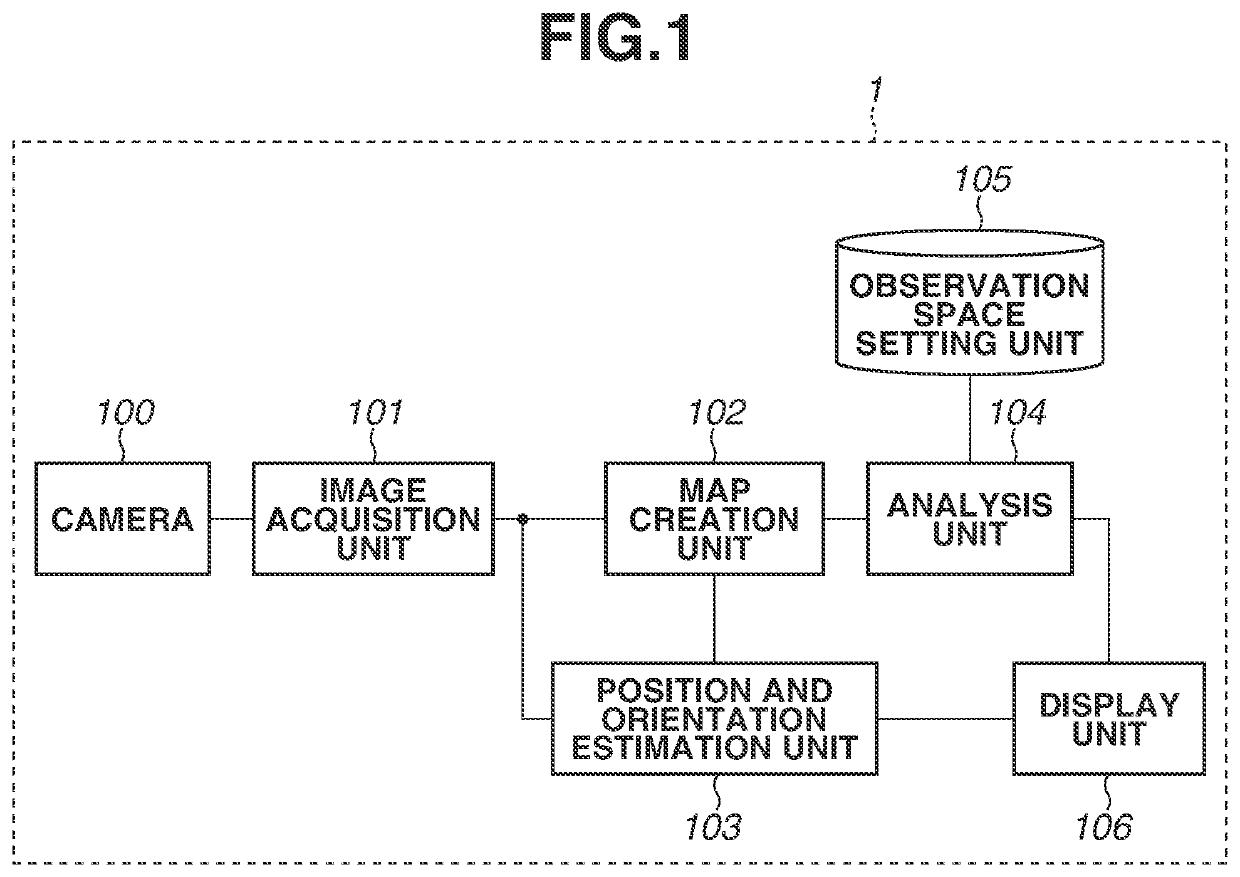
[0045]In the first embodiment, in terms of the processing of step S508 performed by the analysis unit 104, the method for setting the vertex color of the mapped vertex of the polygon mesh 401 to the preset setting color 2 is described. However, the setting of the vertex color of a vertex in the embodiments is not limited to the above method, and is simply required to be a form where information on a keyframe included in a map is reflected.
[0046]For example, in the processing performed in step S508 by the analysis unit 104, the vertex visualization determination may be performed on all the keyframes in the map, and vertex colors may be set in accordance with the number of keyframes determined to be visible. Further, the vertex color may be set in accordance with the distance between the keyframe determined to be visible and the vertex.
second modification
(Second Modification)
[0047]In the first modification, in terms of the processing performed in step S508 by the analysis unit 104, the method for setting the vertex color of the mapped vertex is described. However, the shape of the polygon mesh 401 may be changed to allow distinguishing the mapped vertex from the other vertices.
[0048]For example, the analysis unit 104 may produce a projection or depression on the polygon mesh 401 by moving the coordinates of the mapped vertex in the direction of a normal. The analysis unit 104 may add a straight line representing the line of sight E to the mapped vertex to illustrate the direction, on the display unit106, in which the vertex has been captured in the keyframe. The length of the straight line representing the line of sight E may be fixed or changed depending on the length of the line of sight E.
[0049]It has been described assuming that the analysis unit 104 in the first embodiment creates a CG model for visualizing a space captured in ...
third modification
(Third Modification)
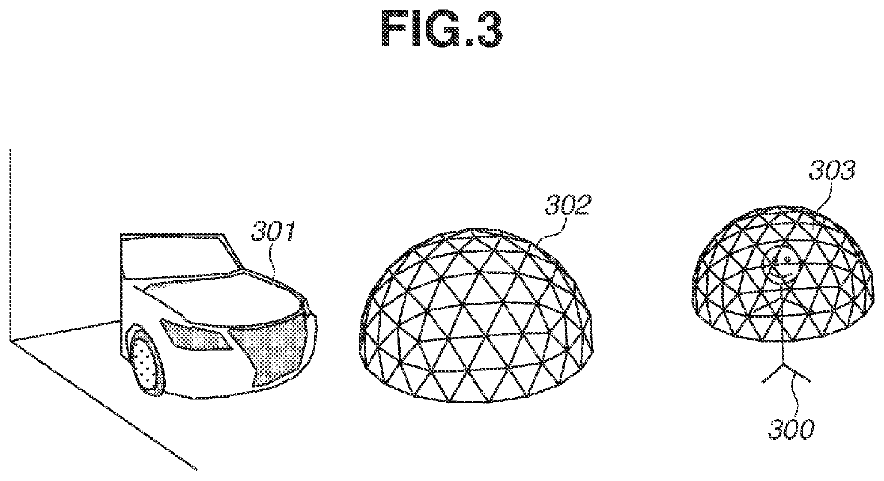
[0054]In the second embodiment, each vertex of the polygon mesh 401 is set to a vertex color in accordance with a spot area to which a keyframe where the vertex has been determined to be visible belongs. However, the vertex may be visible on a plurality of keyframes depending on the vertex, and spot areas to which the keyframes belong may be different. Further, if the color of each vertex of one polygon mesh 401 is different, it may be difficult for the user 300 to identify a space where the position-and-orientation of the camera 100 can be estimated with high accuracy. Hence, the analysis unit 104 may determine to which spot area the position of the camera 100 belongs, and set only a keyframe belonging to the same spot area as the camera 100, as a process target, among the keyframes included in the map created by the map creation unit 102. Specifically, in step S801 in the second embodiment, only a keyframe belonging to the same spot area as the camera 100 may b...
PUM
 Abstract
Description
Claims
Application Information
 - R&D
- Intellectual Property
- Life Sciences
- Materials
- Tech Scout
- Unparalleled Data Quality
- Higher Quality Content
- 60% Fewer Hallucinations
Browse by: Latest US Patents, China's latest patents, Technical Efficacy Thesaurus, Application Domain, Technology Topic, Popular Technical Reports.
© 2025 PatSnap. All rights reserved.Legal|Privacy policy|Modern Slavery Act Transparency Statement|Sitemap|About US| Contact US: help@patsnap.com