Motion estimation apparatus and control method thereof

a technology of motion estimation and video signal, which is applied in the field of estimating the motion amount of interlaced video signal, can solve the problems of line flicker, high noise, and high probability of motion amount determination, and achieve the effect of higher accuracy and favorable interpolated imag

Inactive Publication Date: 2011-12-20
CANON KK
View PDF19 Cites 5 Cited by
  • Summary
  • Abstract
  • Description
  • Claims
  • Application Information

AI Technical Summary

Benefits of technology

[0010]Having been conceived in light of the problem described above, it is an object of the present invention to provide a technique capable of generating a favorable interpolated image by estimating the motion amount of a video image with higher accuracy.
[0017]According to the present invention, it is possible to achieve highly accurate estimation of the motion amount of a target pixel for motion estimation between two adjacent lines in a current field when generating a non-interlaced video signal from an interlaced video signal. Furthermore, by using this estimation result, a favorable non-interlaced video signal can be generated.

Problems solved by technology

For example, if interpolation is performed with the image signal of a current field for a still area, narrow horizontal stripes disappear, causing a flicker.
Conversely, if interpolation is performed with the image signal of a previous field for a moving area, a motion blur occurs, causing combing noise.
However, as shown in FIG. 2, when the pixels from the upper and lower lines are calculated, the following problem remains.
More specifically, because motion estimation is performed using a difference in values between the computed result and the pixel located in the same position as the pixel for interpolation in the previous field, motion amount is likely to be determined even for a still area, and line flicker therefore occurs.

Method used


Image

  • Motion estimation apparatus and control method thereof
  • Motion estimation apparatus and control method thereof
  • Motion estimation apparatus and control method thereof

Examples


first embodiment

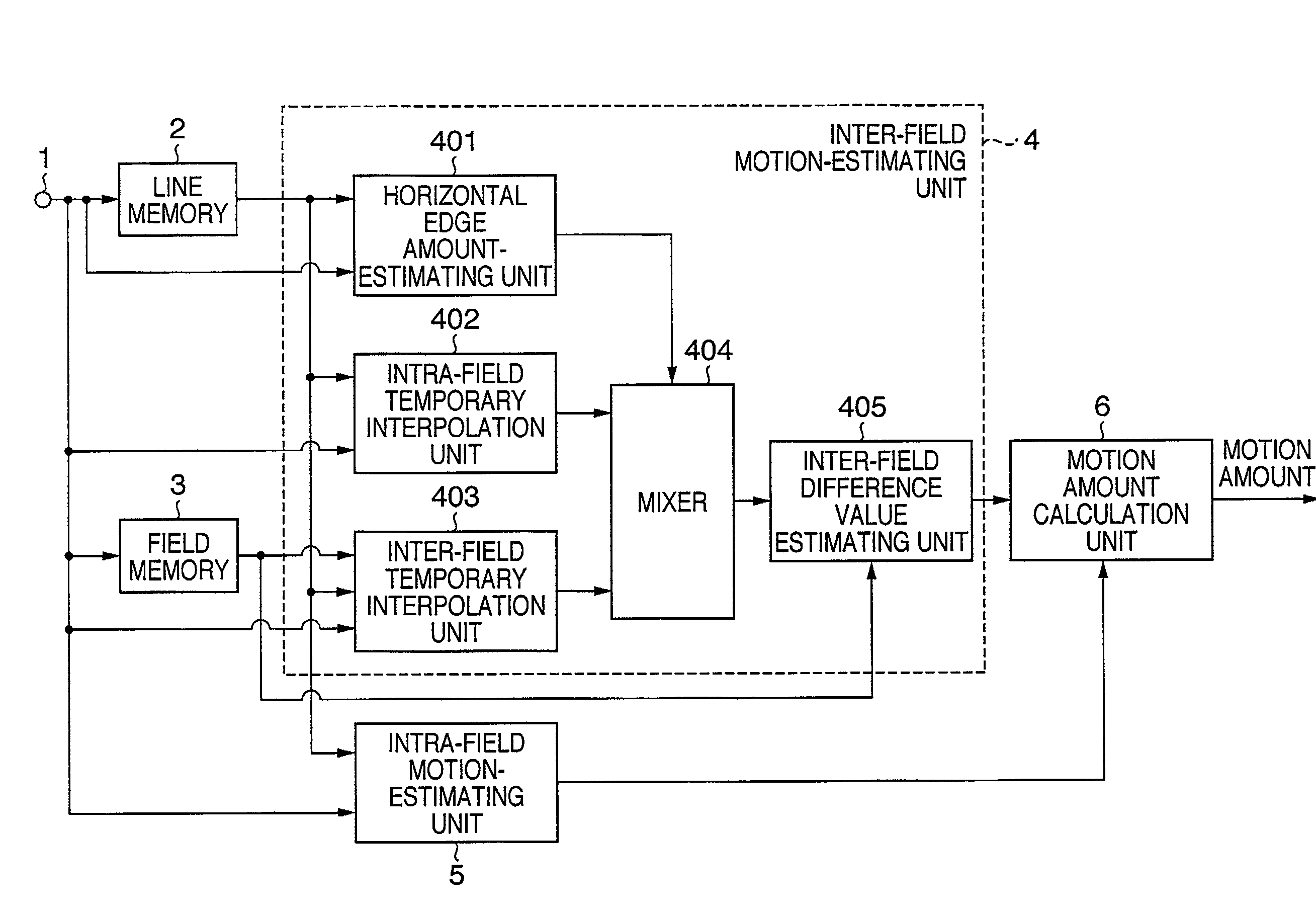
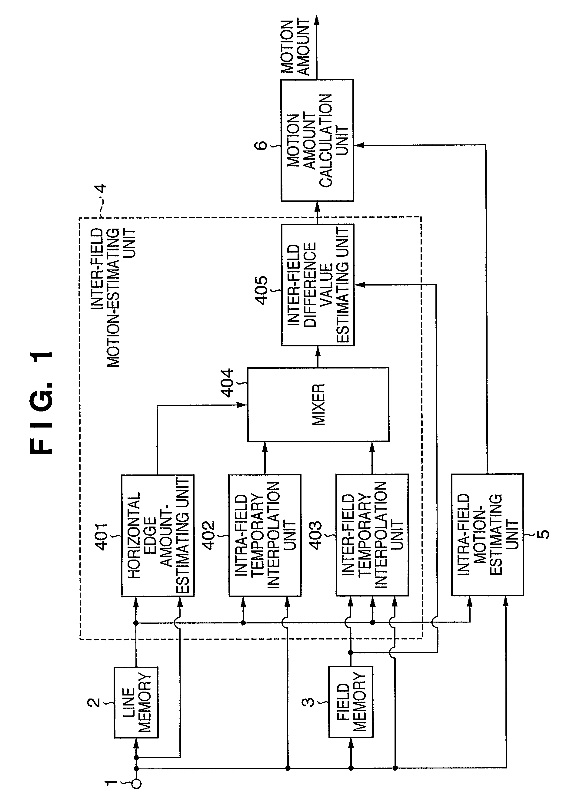
[0030]FIG. 1 is a block diagram showing an example of a motion estimation apparatus according to the first embodiment. For the sake of simplicity, an example is described in which the target to be processed is the luminance signal of a video signal, but it should be understood that the present invention is not limited thereto.

[0031]The motion estimation apparatus shown in FIG. 1 includes an input terminal 1, a line memory 2, a field memory 3, an inter-field motion-estimating unit 4, an intra-field motion-estimating unit 5, and a motion amount calculation unit 6.

[0032]The input terminal 1 inputs an interlaced video signal. The line memory 2 has a capacity for storing one line's worth of the interlaced signal is inputted by the input terminal 1. The field memory 3 has a capacity for storing one field's worth of the interlaced signal is inputted by the input terminal 1. The inter-field motion-estimating unit 4 estimates a motion amount between a current field and a previous field. The ...

second embodiment

[0072]Next, the second embodiment shall be described. In this embodiment, an example is shown in which the configuration of the first embodiment described above is applied to a progressive scanning conversion apparatus.

[0073]FIG. 4 is a diagram showing the configuration of an apparatus according to the second embodiment. The differences between the configurations of FIGS. 4 and 1 are that a pixel interpolation unit 7 is added in FIG. 4, and the inter-field motion-estimating unit 4 of FIG. 1 is indicated by reference numeral 9 in FIG. 4. Accordingly, a horizontal edge amount estimating unit 901, an intra-field temporary interpolation unit 902, an inter-field temporary interpolation unit 903, a mixer 904, and an inter-field difference value estimating unit 905 are identical to the components 401 to 405 of FIG. 1, respectively, and thus their descriptions will be omitted.

[0074]The pixel interpolation unit 7 mixes the pixel Xc located in the same position as the pixel for interpolation ...

third embodiment

[0078]The first and second embodiments described above may be implemented by a generic information processing apparatus, such as a personal computer, and a computer program that causes the information processing apparatus to execute the first and second embodiments. Such an example shall be described below as the third embodiment.

[0079]FIG. 7 is a block diagram showing the configuration of an information processing apparatus according to the third embodiment.

[0080]In FIG. 7, reference numeral 301 denotes a central processing unit (hereinafter referred to as “CPU”) that performs control of the entire apparatus and various processes. Reference numeral 302 denotes a memory configured of a ROM that stores a BIOS and a boot program, and a RAM serving as a work area for the CPU 301. Reference numeral 303 denotes an instruction input unit configured of a keyboard, a pointing device such as a mouse, and various switches. Reference numeral 304 denotes an external storage device (e.g., a hard...


PUM


Abstract

The present invention enables highly accurate estimation of a motion amount of a target pixel for motion-estimation located between two adjacent lines in a current field when generating a non-interlaced video signal from an interlaced video signal. To achieve this aim, an inter-field motion-estimating unit estimates a motion amount between a current field and a previous field. An intra-field motion-estimating unit estimates a motion amount within a current field. A motion amount calculation unit calculates a final motion amount based on the inter-field motion amount estimated by the inter-field motion-estimating unit and the intra-field motion amount estimated by the intra-field motion-estimating unit, and then outputs the motion amount.

Description

BACKGROUND OF THE INVENTION[0001]1. Field of the Invention[0002]The present invention relates to a technique for estimating the motion amount of an interlaced video signal.[0003]2. Description of the Related Art[0004]Currently, typical video signal processing apparatuses handle interlace-scanned image signals.[0005]Flicker commonly occurs in horizontal edge portions of an interlace-scanned image. As a means for addressing this problem, a technique is known in which interpolation is performed on interlace scan lines so as to generate and output a progressive-scan image signal.[0006]Also, a technique is known in which, when converting into progressive scanning, the motion amount of an image is estimated, and the signal of a previous field and that of a current field are combined according to the result of the motion estimation to generate an interpolation signal. According to this technique, the condition of the interpolation signal varies according to the accuracy of the result of th...

Claims


Application Information

Patent Timeline
Patent Type & Authority Patents(United States)
IPC IPC(8): G06K9/36G06K9/46H04N7/01
CPCH04N5/144H04N7/012H04N7/01
Inventor AOKAGE, HIRONORI
Owner CANON KK
Why Eureka
Try Eureka