Door system for a vacuum train

a vacuum train and door system technology, applied in railway stations, transportation and packaging, ways, etc., to achieve the effect of reducing tim

Active Publication Date: 2022-11-08
SWISS TRANSPORTATION RES INST AG
View PDF25 Cites 0 Cited by
  • Summary
  • Abstract
  • Description
  • Claims
  • Application Information

AI Technical Summary

Benefits of technology

[0005]Hence, it is an object of the invention to provide a door system for a vacuum train. The door system shall allow for a swift opening of the doors of the vehicle and the doors of the station in order to minimize the time that the vehicle has to be at a standstill at the station, in particular at a standstill without allowing passengers and / or goods to enter or leave the vehicle.
[0007]The inflatable and deflatable seal as claimed provides for a mechanically simple solution, essentially without moving parts for sealing, except for the expanding and contracting seal itself. This allows for a quick sealing action to isolate both doors from the vacuum within the pipe or tunnel. It also allows the positioning of the seal near to the doors of the vehicle and the station. Thereby the amount of air, which has to be introduced into the space between the doors resp. into the space between the vehicle and station before the corresponding doors can be opened can be minimized. And as well and very important, as explained below, it allows to minimize the time for removing the air from the sealed area between the doors resp. between the vehicle and the wall of the pipe after the doors have been closed. The ring shaped seal can be of circular or rectangular or quadratic ring shape. The cross section of the ring-shaped seals can be circular or may have a different shape, which is suited to their function. The material or the material combination from which the ring-shaped seal is made allows for an expansion to its inflated size and shape and for deflation. The seal may be made of reinforced rubber as for example known from automobile tyres and may additionally have an outer layer from a softer material, in particular a plastic material, which allows for a good sealing against the vehicle hull and the inside of the pipe or tunnel. It must be suitable for the given environment with vacuum and in particular shall not release gases and vapours into the vacuum. It may as well be possible to include a material improving the sealing properties on the hull of the vehicle and on the inside of the pipe or tunnel at the position where the ring-shaped seal will contact the hull and the inside of the pipe or tunnel in its inflated state, in order to improve the sealing contact of the ring-shaped seal with the vehicle and the pipe or tunnel. The contact areas on both the hull and the pipe / tunnel wall can also have a special shape or form eg. rills or grooves, respectively to enhance the sealing effect.
[0009]The ring shaped seal is preferably inflated pneumatically by a gas and deflated by removing the gas from the seal. The gas may be air or an inert gas or an air / inert gas mixture. As well the ring shaped seal may be inflated by a liquid and deflated by removing the liquid from the seal. The liquid may include a percentage of gas in order to improve the compressibility of the seal and thus to improve the sealing properties towards the vehicle hull and the inside of the pipe or tunnel.

Problems solved by technology

The vacuum in the space between the vehicles and the walls of the pipes is an obstacle.

Method used


Image

  • Door system for a vacuum train

Examples


Embodiment Construction

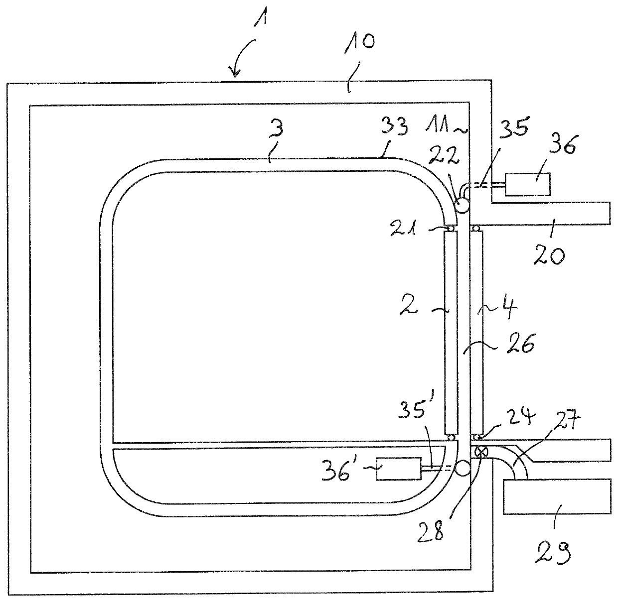
[0014]An example of a vacuum train 1 is shown by the FIGURE in a vertical cross section view. A vacuum train comprises basically a vehicle and a track for the vehicle which is designed as a pipe (or tunnel) from which the air has been partially or completely evacuated to reduce or eliminate aerodynamic drag. With magnetic levitation (or similar means) rolling resistance can also be eliminated. An outstanding performance and efficiency becomes possible. The cabin of the vehicle is obviously pressurised to a level which is comfortable for the passengers and crew (1.0 Bar). A vacuum train is shown in a much simplified schematic view in order to explain the basic features. Accordingly, the vacuum train 1 includes at least one vehicle 3 with a passenger cabin 13.

[0015]This vehicle can be propelled and guided in the pipes or tunnel by a MAGLEV system (Magnetic Levitation system) or by any other suitable means. The MAGLEV system respectively the system for propulsion and guidance is not sh...


PUM


Abstract

A door system for a vacuum train includes at least one vehicle with at least one vehicle door and a track including at least one evacuated pipe that guides and propels elements within the pipe. The track includes at least one station outside of the pipe with at least one station door arranged within the wall of the pipe to selectively close and open the station towards the pipe. The vehicle door and the station door being arranged in a corresponding position when the vehicle is at rest, so that persons can leave or enter the vehicle when the vehicle door and the station doors are open at the rest position. The door system comprises at least one inflatable ring shaped seal (22) which surrounds both doors when the doors are in their corresponding position and which seals in its inflated position both doors against the vacuum within the pipes.

Description

CROSS-REFERENCE TO RELATED PATENT APPLICATIONS[0001]This application is a U.S. National Stage Application under 35 U.S.C. § 371 of International Patent Application No. PCT / EP2017 / 073310, filed Sep. 15, 2017, which is incorporated by reference in its entirety. The International Application was published on Mar. 21, 2019, as International Publication No. WO 2019 / 052656 A1.TECHNICAL FIELD[0002]The invention relates to a door system for a vacuum train, wherein the vacuum train comprises at least one vehicle with at least one vehicle door and a track for the vehicle, which track comprises at least one evacuated pipe and / or tunnel for the vehicle and at least one station outside of said pipe and / or tunnel with at least one station door being arranged within the wall of the pipe and / or tunnel to selectively close and open the station towards the pipe and / or tunnel and the vehicle, and wherein the vehicle door and the station door are arranged to be in a corresponding position when the vehi...

Claims


Application Information

Patent Timeline
Patent Type & Authority Patents(United States)
IPC IPC(8): B61B13/10B61B1/02B61D19/02
CPCB61B1/02B61B13/10B61D19/02Y02T30/00F16J15/46E01F1/00
Inventor BAHMAN, RAMON ALEXANDERBAHMAN, AURELIUS CHRISTIAN
Owner SWISS TRANSPORTATION RES INST AG
Why Eureka
Try Eureka