Turbine housing and turbo charger provided with same

a technology of turbine housing and turbo charger, which is applied in the direction of combustion engines, machines/engines, leakage prevention, etc., can solve the problems of dissipation of thermal energy of exhaust gas introduced into the turbine housing, and achieve the effect of reducing the amount of thermal energy loss and high mass productivity

Active Publication Date: 2022-11-22
MITSUBISHI HEAVY IND ENGINE & TURBOCHARGER LTD
View PDF36 Cites 0 Cited by
  • Summary
  • Abstract
  • Description
  • Claims
  • Application Information

AI Technical Summary

Benefits of technology

[0020]According to the present invention, it is possible to provide a high-mass productivity turbine housing capable of reducing the amount of thermal energy loss of the exhaust gas introduced into the turbine housing and the thermal stress generated at a flow passage part and a turbo charger provided with the same.

Problems solved by technology

However, the thermal energy of the exhaust gas introduced into the turbine housing dissipates in part to the outside of the turbine housing during passage through a scroll flow passage part (scroll part) in the turbine housing.

Method used


Image

  • Turbine housing and turbo charger provided with same
  • Turbine housing and turbo charger provided with same
  • Turbine housing and turbo charger provided with same

Examples


first embodiment

[0033]Hereinafter, a turbo charger 100 according to a first embodiment of the present invention will be described with reference to accompanying drawings.

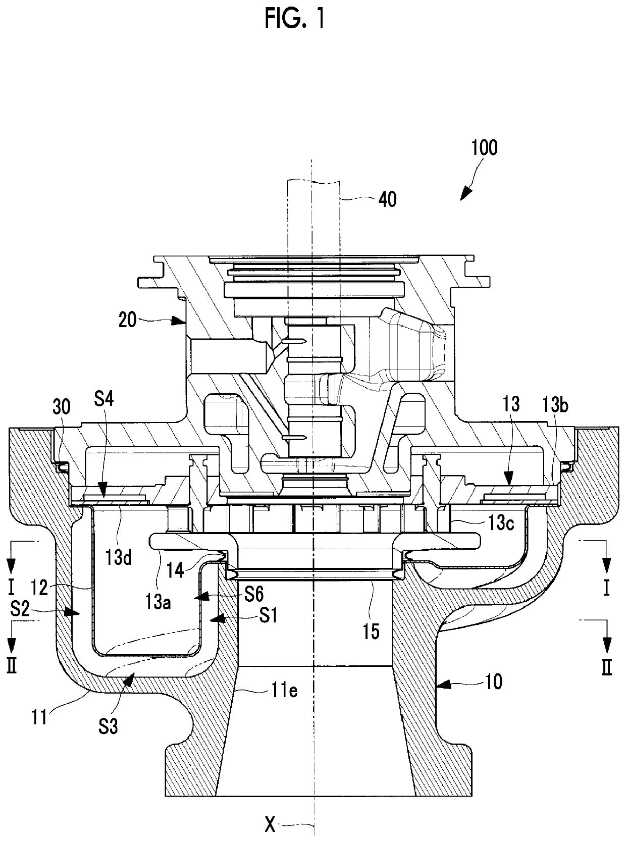
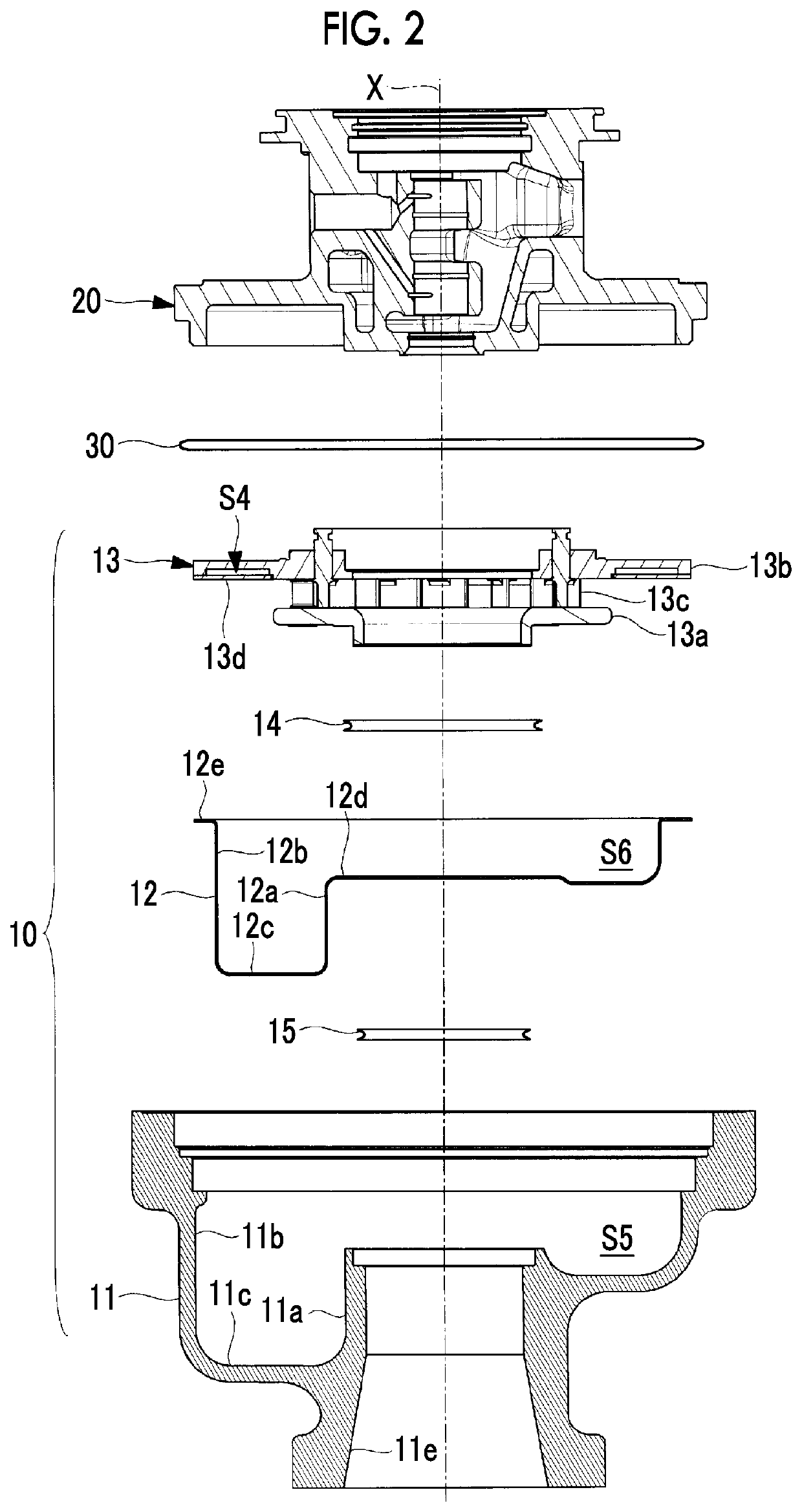
[0034]The turbo charger 100 of the present embodiment is, for example, a variable geometry (VG) turbo charger provided with a variable nozzle mechanism (nozzle part) 13. The VG turbo charger has the variable nozzle mechanism 13 in a turbine housing 10. The variable nozzle mechanism 13 appropriately adjusts the rotation speed of a turbine wheel by adjusting the flow rate of exhaust gas introduced by nozzle opening degree adjustment. The turbo charger 100 generates compressed air and supplies the compressed air to an internal combustion engine by rotating an impeller of a compressor connected to the turbine wheel via a rotating shaft 40.

[0035]As illustrated in FIG. 1 (longitudinal cross-sectional view) and FIG. 2 (exploded view), the turbo charger 100 of the present embodiment is provided with the turbine housing 10 in which the turb...

second embodiment

[0076]Next, a turbo charger 100A according to a second embodiment of the present invention will be described.

[0077]The first heat-shielding space S1, the second heat-shielding space S2, the third heat-shielding space S3, and the fourth heat-shielding space S4 are spaces where no other members are disposed and air is used as a heating insulating material in the turbo charger 100 according to the first embodiment. In the turbo charger 100A of the present embodiment, the first heat-shielding space S1, the second heat-shielding space S2, the third heat-shielding space S3, and the fourth heat-shielding space S4 are filled with a heat-shielding member 16.

[0078]Used as the heat-shielding member 16 is, for example, a ceramic fiber containing alumina (Al2O3) and silica (SiO2) as main components. The heat insulation properties of the first heat-shielding space S1, the second heat-shielding space S2, the third heat-shielding space S3, and the fourth heat-shielding space S4 are further improved...


PUM


Abstract

Provided is a turbine housing (10) having: a housing part (11) that forms a spiral space (S5) extending around a rotating shaft (40); a heat-shielding core (12) which is disposed in the spiral space (S5) and forms a spiral exhaust gas flow passage (S6) in which exhaust gas introduced from an exhaust gas introduction port flows; and a variable nozzle mechanism (13) that guides the exhaust gas to a turbine wheel, wherein heat-shielding spaces (S1, S2, S3) are formed between the inner circumferential surface of the housing part (11) and the outer circumferential surface of the heat-shielding core (12), and wherein the heat-shielding core (12) has a first flange part (12d) and a second flange part (12e) and is fixed between the variable nozzle mechanism (13) and the housing part (11) while a first sealing (14) is interposed between the first flange part (12d) and the variable nozzle mechanism (13).

Description

TECHNICAL FIELD[0001]The present invention relates to a turbine housing and a turbo charger provided with the same.BACKGROUND ART[0002]Known in the related art is a turbo charger supplying pressurized air to an intake manifold by rotating a turbine wheel by using the energy of exhaust gas guided from an engine and rotating a compressor wheel provided coaxially with the turbine wheel (see, for example, PTL 1 and PTL 2).[0003]In order to improve the efficiency of the turbo charger, it is necessary to guide the thermal energy of the exhaust gas introduced into the turbine housing to a turbine with the loss of the thermal energy minimized. However, the thermal energy of the exhaust gas introduced into the turbine housing dissipates in part to the outside of the turbine housing during passage through a scroll flow passage part (scroll part) in the turbine housing.[0004]In PTL 1, a heat insulation layer that has a heat insulation core covered with a sheet metal shell is disposed as a sepa...

Claims


Application Information

Patent Timeline
Patent Type & Authority Patents(United States)
IPC IPC(8): F01D25/26
CPCF01D25/26F05D2220/40F05D2240/15F02B37/24F01D25/145F01D17/165F01D9/026F01D11/003F01D25/24Y02T10/12
Inventor ARAI
Owner MITSUBISHI HEAVY IND ENGINE & TURBOCHARGER LTD
Why Eureka
Try Eureka