Model railroad occupancy detection equipment

a technology for occupancy detection and equipment, applied in the direction of model railways, railway signalling and safety, toys, etc., can solve the problems of imposing tough detection challenges, placing sensitivity and other burdens on the transponder detection device, and performing transponder operations at lower current levels, so as to achieve more layout control possibilities and improve the design of occupancy detectors

Inactive Publication Date: 2001-06-28
IRELAND ANTHONY JOHN
View PDF0 Cites 45 Cited by
  • Summary
  • Abstract
  • Description
  • Claims
  • Application Information

AI Technical Summary

Benefits of technology

[0013] Improvements in occupancy detector design and transponder capabilities described in this invention allow more layout control possibilities. These improvements are best employed in a single combined detection device, but may also be employed separately as required.
[0017] The capability to detect feedback information coded by units on the layout permit many valuable and unique new capabilities to be created. For example, it is then possible to read state information back from rolling stock or locomotives or even devices with fixed connections to the track. It is possible to receive sound synchronization information from steam locomotives moving on the layout, so a surround sound unit can create realistic wheel synchronized chuff sounds. A function can be created that detects the placement of a new unit on the layout that is not being controlled or addressed by any user, to search for its control address and then alert the layout supervisor. This feature can also detect the removal from layout control of a controlled unit due to derailment or human intervention.

Problems solved by technology

Smaller, less expensive and more reliable transponder or decoder electronics in locomotives require transponders with feedback current pulses with magnitudes less than typical motor current draws, but this places sensitivity and other burdens on the transponders detection devices.
Attempting to perform transponder operations at lower current levels than model locomotive motors typically draw imposes some tough detection challenges.
In this situation the occurrence of extraneous cross talk signals or echoes when multiple detectors are connected to a single track power booster cause ambiguity in transponder location.
Transponder detectors are not able to discriminate echoes by the magnitude of current pulses they may see, since it is not possible to accurately predict the current that any transponder or track arrangement will yield.

Method used


Image

  • Model railroad occupancy detection equipment
  • Model railroad occupancy detection equipment
  • Model railroad occupancy detection equipment

Examples


Embodiment Construction

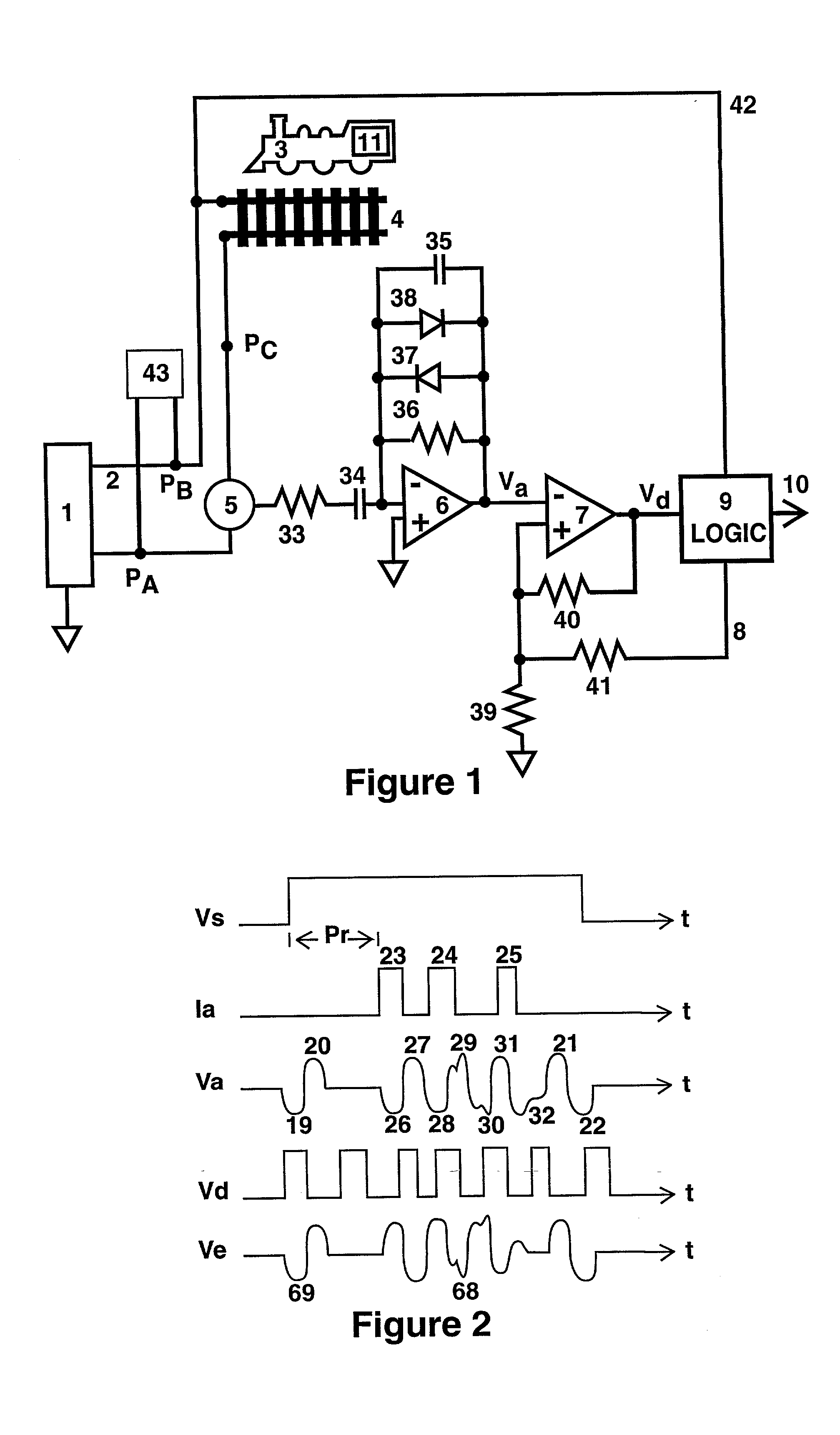
[0025] The track power booster element 1 in FIG. 1, is connected to the layout tracks, 4, that are to be controlled and detected via the feeder wiring, 2. One of the feeder wires conducting power and control signals to the tracks, 4, is connected to a detection current sensor device, 5. The item we wish to detect, typically a locomotive or piece of rolling stock, 3, containing a current load and possibly a transponder device, 11, is in electrical contact with the track, 4.

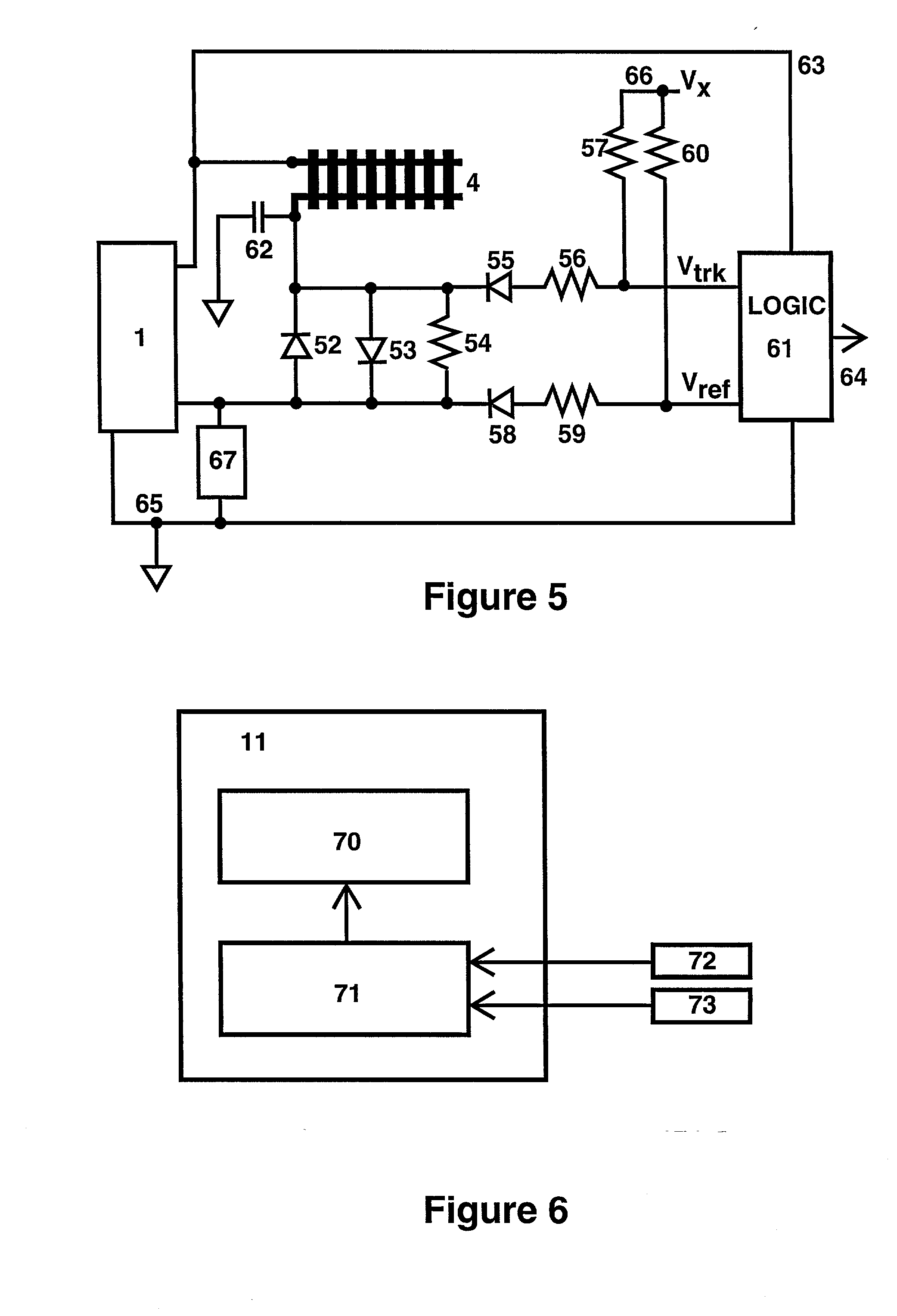
[0026] Transponder acknowledgement current pulses, designated in this description as Ia, are encoded and generated by transponder current generating device, 70 in FIG. 6, at appropriate time periods determined by transponder timing generator, 71 in FIG. 6, in response to system commands that are addressed to, or interrogate, the transponder. This corresponds to existing transponder techniques. The exact command encoding format used by the control system to drive the track power booster and hence the rails may corre...


PUM


Abstract

New techniques are presented for occupancy detection methods employed in the control, automation and operation of scale Model railroad layouts that permit new types of capabilities to be incorporated into the railroad. The invention allows for a universal occupancy detector that can automatically configure itself to work on common rail or direct home wiring arrangements. This occupancy detector is able to work with large track feeder parasitic or stray capacitances and is also able to determine when any direct home track section is energized.

Description

[0001] This specification is a Divisional application following on from Ser. No. 09 / 354,506 dated Jul. 15, 1999, examined by M.T.Le / GAU 3617.BACKGROUND OF INVENTION[0002] This invention pertains to the field of control systems for scale model railroad layouts, and specifically to improvements in elements of block occupancy and location detection methods that are employed on model railroads.[0003] Improvements in the miniaturization, increased capability and decreasing costs of electronics components coupled with new circuit designs have allowed the application of new techniques to model railroad layouts. These advances permit the creation of layouts with greater levels of sophistication, automation and real time feedback of operating states from many types of devices on or around the layout.[0004] Track occupancy detection for model railroads has been used for many years. It is used for both operation of signal systems and also to display track state for areas out of direct view of ...

Claims


Application Information

Patent Timeline
Patent Type & Authority Applications(United States)
IPC IPC(8): A63H19/24
CPCA63H19/24
Inventor IRELAND, ANTHONY JOHN
Owner IRELAND ANTHONY JOHN
Why Eureka
Try Eureka