
Convertible motor vehicle door

a technology for convertible motor vehicles and doors, applied in the direction of roofs, vehicle components, transportation and packaging, etc., can solve the problem of complex arrangemen

Inactive Publication Date: 2001-09-27
WEBASTO VEHICLE SYST INT
View PDF0 Cites 23 Cited by
  • Summary
  • Abstract
  • Description
  • Claims
  • Application Information

AI Technical Summary

Benefits of technology

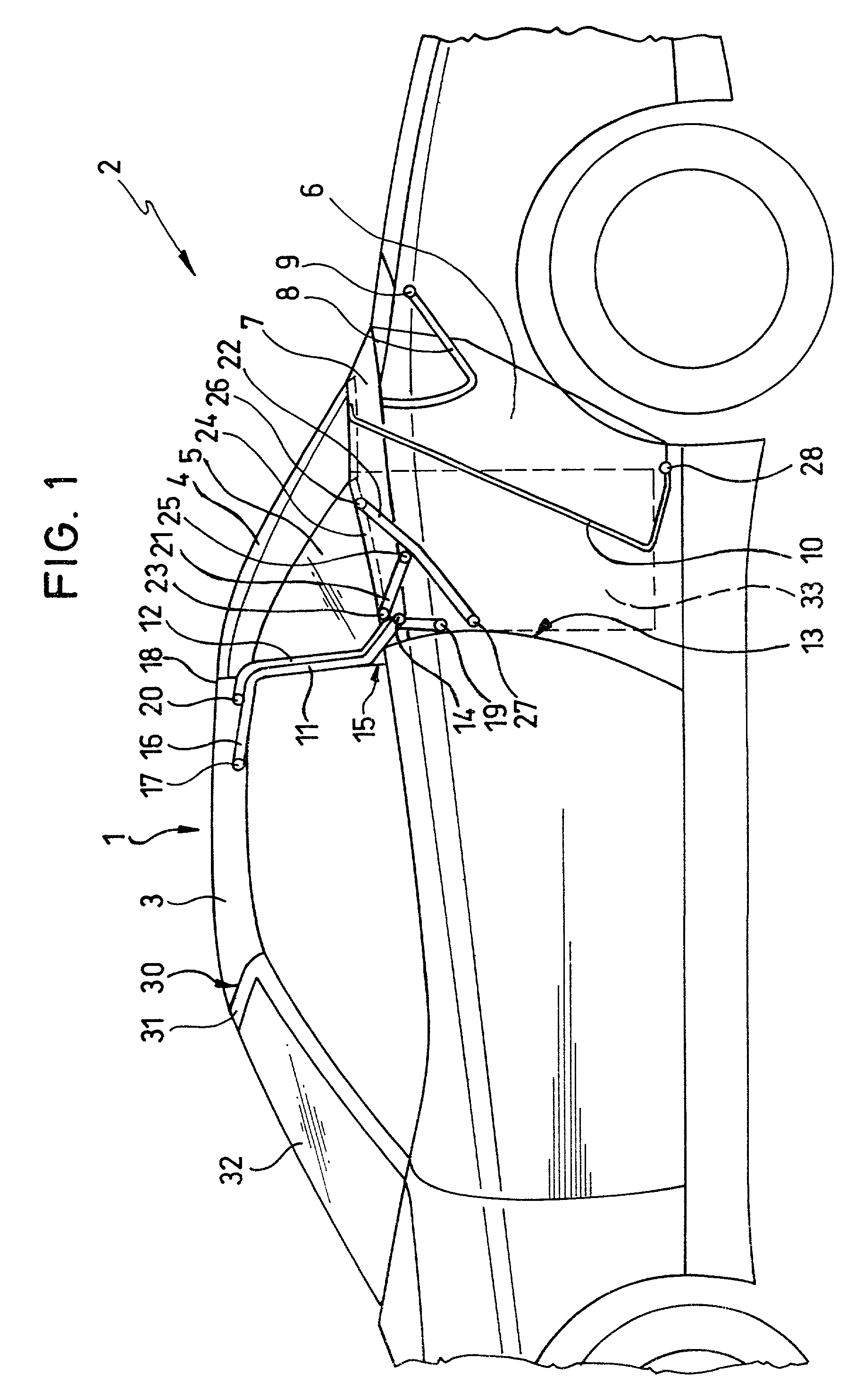
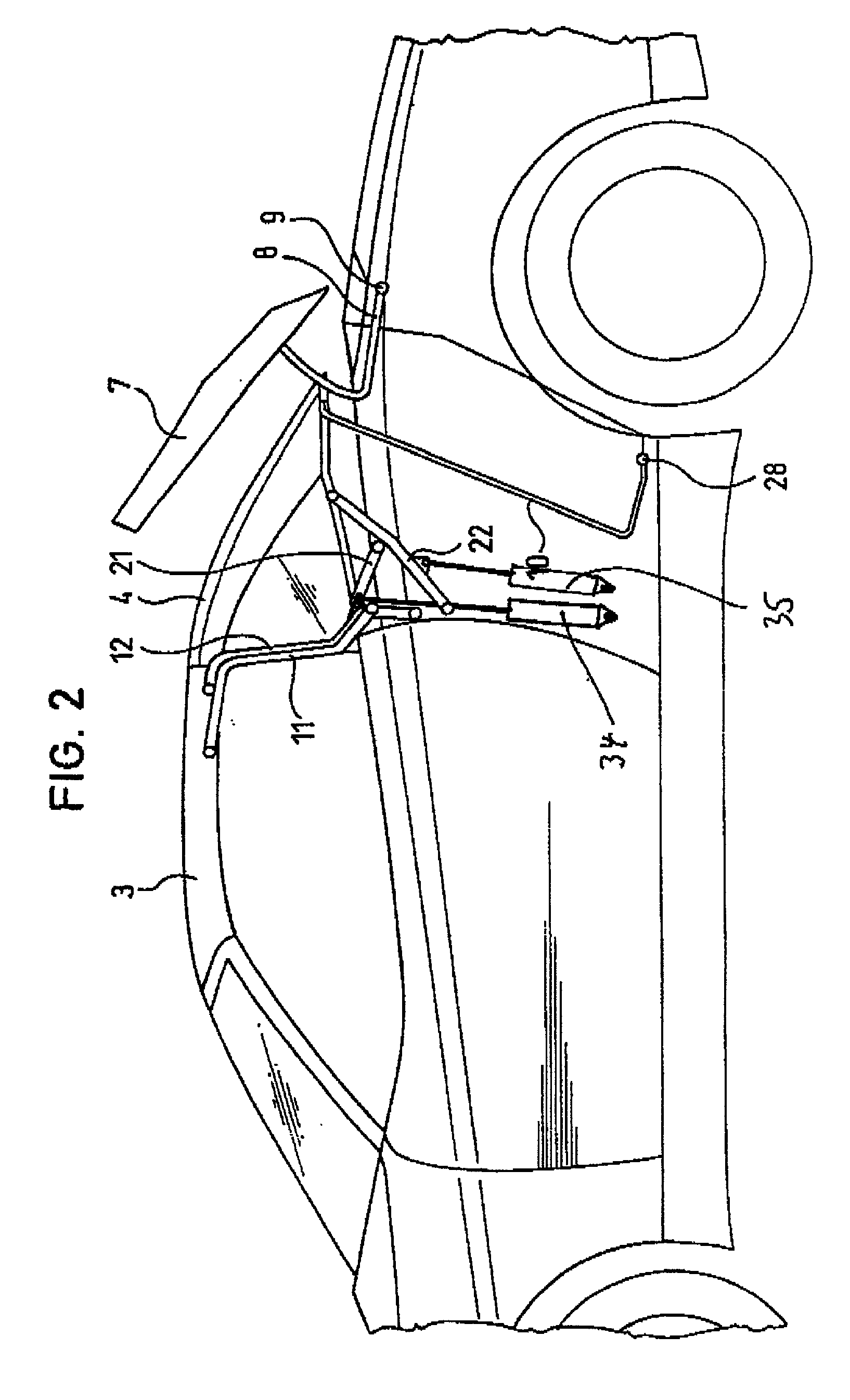
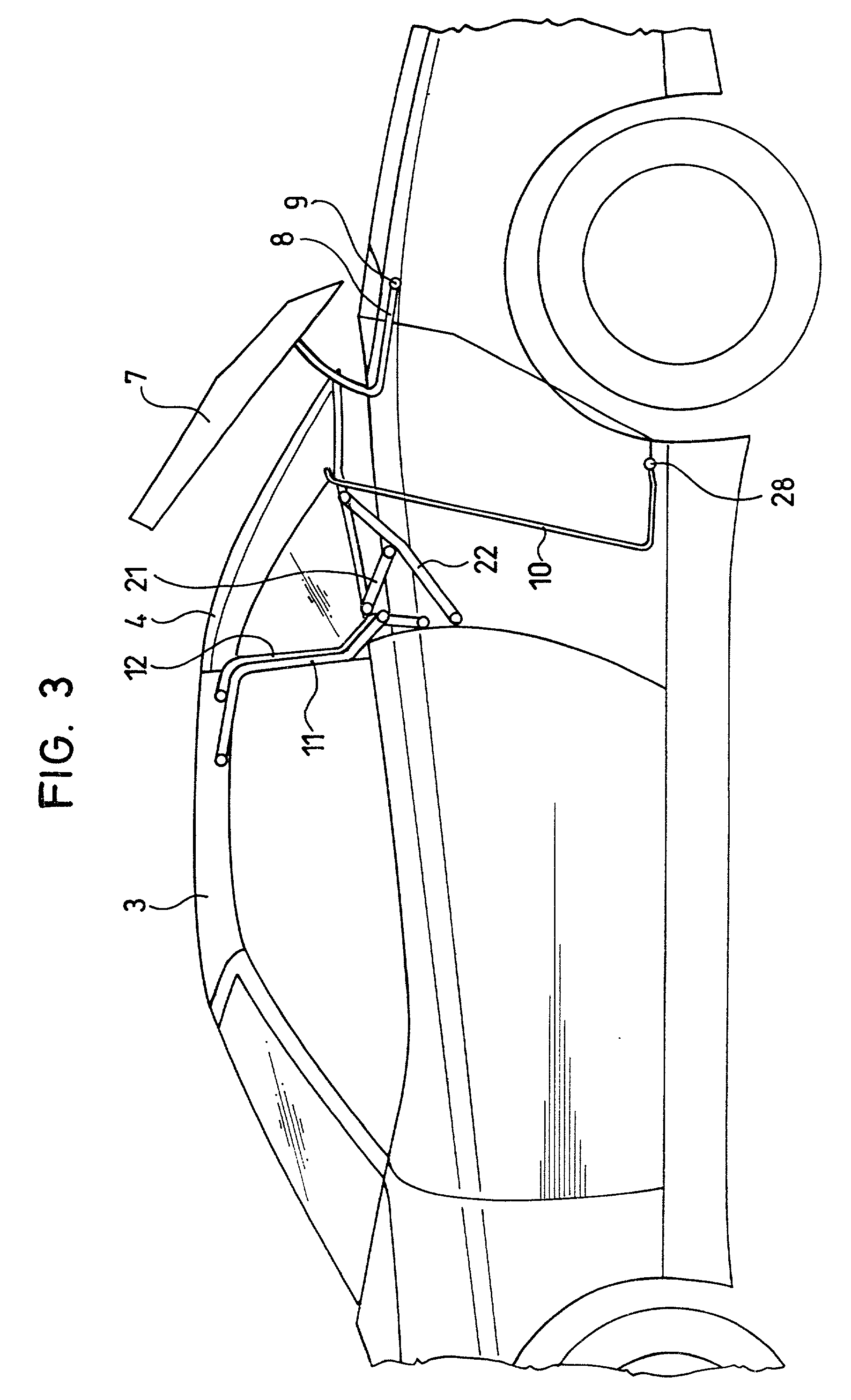
[0008] Preferably, the rear element with the roof element closed can be deposited in the stowage space for the folding roof so that it can be operated when driving with the motor vehicle roof partially open. Here, the rear element can be deposited and also removed independently of the roof element in order to close the motor vehicle roof again. In one feasible configuration, the cover of the stowage space for the folding roof, which is pivotally mounted on the body, can be swung upward from its closed position with the rear roof element closed, enabling a simple sequence of motions when the rear roof element is deposited.
[0009] Preferably, the lever means which supports the front roof element contains two levers which form a four-bar mechanism. Depending on the chosen positions of the joints of the two levers, the pivoting motion of the front roof element can be easily dictated and adjusted. In a comparable configuration, the lever means which supports the rear roof element can have two rods which form a four-bar mechanism.
[0012] When the inside cover is made at least partially flexible, a cargo space provided directly behind the seats can be widened into the stowage space for the folding roof with the motor vehicle roof closed without the inside cover having to be removed.
[0015] For easy and still reliable attachment of the joints which support the levers and rods on the body side, it can be provided that they are located on a bearing plate on the body.

Problems solved by technology

However, this horizontal deposition of the front roof element and the rear roof element requires a large stowage space which extends into the trunk and makes the latter smaller.
However, this arrangement is very complex, the rear roof element being composed of a rear roof part and a pair of side window panel members, the rear roof part sliding forward into the front roof element for lowering with it, while the side window panel members are swung down separately in advance of joint lowering of the rear roof part with the front roof element.

Method used


Image

  • Convertible motor vehicle door
  • Convertible motor vehicle door
  • Convertible motor vehicle door

Examples


Embodiment Construction

[0025] The motor vehicle roof 1 of a convertible automobile 2 is made as a convertible hardtop having a rigid front roof element 3 and a rigid rear roof element 4 which can contain a rear window 5. The motor vehicle roof 1 can be converted into an open-top configuration by the front roof element 3 and the rear roof element 4 being deposited essentially vertically in a stowage space 6 for the folding roof which is located behind the seats and in front of the trunk, i.e., between the wheel well for the rear wheels and the rear seats. The cover 7 of the stowage space 6 is supported on the body via a rod 8 having a rear pivot joint 9 and laterally surrounds the lower edge of the rear roof element 4 to the rear in somewhat of a U-shape. The cover 7 is able to be folded up from its closed position in which it covers the stowage space 6 with the motor vehicle roof 1 closed and in which it tightly adjoins the lower edge of the rear element 4 (the motor vehicle roof is described using the be...


PUM


Abstract

A convertible roof for a motor vehicle with a front roof element (3) and a rear roof element (4), which are supported to pivot on the body by a respective lever arrangement and can be deposited in a stowage space (6) which can be covered by a pivotable cover (7) of the stowage space. The front roof element (3) and the rear roof element (4) are deposited essentially in a vertical arrangement in the stowage space (6) for the roof elements. The cover (7) of the stowage space (6) for the roof elements is pivotally mounted on the body and can swing upward out of its cover position with the rear element (4) closed.

Description

[0001] 1. Field of the Invention[0002] The invention relates to a convertible motor vehicle roof with a front roof element and a rear roof element which are pivotally mounted by lever means on the body and which can be deposited in a stowage space which can be covered by a pivoting cover of the stowage space.[0003] 2. Description of Related Art[0004] German Patent DE 44 35 222 C1 and corresponding U.S. Pat. No. 5,769,483 disclose a motor vehicle roof with a front roof element and a rear roof element in which the roof element, which can be locked on the apron via pivotally coupled roof rods, is pivotably coupled to the body by means of a pivot lever. The rear roof element, which rearwardly adjoins the front roof element, sits on the cover flap of the stowage box for the convertible roof to form a seal and forms the transition to the trunk. The rear roof element is movably supported, via a pivot lever which is supported on the body and which can be pivoted by means of a hydraulic cyli...

Claims


Application Information

Patent Timeline
Patent Type & Authority Applications(United States)
IPC IPC(8): B60J7/14B60J7/12
CPCB60J7/148B60J7/207
Inventor SCHUTT, THOMASMIKLOSI, STEFAN
Owner WEBASTO VEHICLE SYST INT
Learn More