
Improved storage and dispensing container for viscous fluids paints and the like and method of minimizing dripping

a technology of viscous fluid and storage container, which is applied in the direction of pliable tubular containers, liquid handling, caps, etc., can solve the problems of large spillage of contents on the ground, damage to the lid sealing surface, and lack of locking mechanism, so as to minimize paint dripping

Inactive Publication Date: 2001-10-04
THE SHERWIN-WILLIAMS CO
View PDF0 Cites 60 Cited by
  • Summary
  • Abstract
  • Description
  • Claims
  • Application Information

AI Technical Summary

Benefits of technology

[0014] A primary object of the invention, accordingly, is to provide a new and improved paint container and the like embodying a novel method or technique for minimizing paint dripping and in addition simultaneously obviating the other previously described handling and operational disadvantages of current paint can containers.

Problems solved by technology

This arrangement has many operational drawbacks that the industry has put up with for many decades These include the lack of a locking mechanism that would prevent the friction lid, popping off if the can is dropped from a height as little as one meter, with consequent spilling of the contents widely on the ground.
The lid, moreover, must be pried off with a tool to gain access to the paint, which proves a problem if no tool is available.
The prying action, moreover, often damages the lid sealing surface.
The can lip, furthermore, makes a very poor spout When the paint contents are transferred to another container, they must be poured across the grooved upper edge of the can, which inherently retains some of the paint, and the paint running down the outside of the can often obscure the label, potentially reaching the users hands and the bottom surface The can, indeed, must be wiped nearly every time it is poured With the inside of the upper rim trapping paint as it is poured, the user is never able to extract all available paint even if a brush is used.
The circular shape of the can opening, in addition, is ineffective for wiping a flat brush clean of excess paint.
Every time paint is poured from a can, the groove that accepts the lid fills with paint and it is very difficult to clean completely.
After repeated opening, pouring, and closing, in addition, the mating surface becomes fouled and the friction seal fails.
Perhaps the biggest drawback of the current paint can, however, resides in the splattering of paint from the groove as the lid is pounded back on The pounding of the lid often damages both sealing surfaces, which again can cause the seal to fail Furthermore, paint in and around the groove can dry out and flake, leading to paint contamination each time the can is jostled While metal cans are coated to prevent rust, this coating often fails, which leads to rust and paint contamination Paint cans, in addition, do not stack well, and little disturbance is needed to cause them to slide off of one another.
As an example, U.S. Pat. No. 5,669,526 discloses a plastic paint can that has a small-diameter, collapsible spout, non-contaminating lid seal, and straight edge formed in the can opening to facilitate brush wiping This configuration, however, only addresses problems of paint contamination, messy pouring, and non-uniform brush wiping inherent in the conventional metal paint can The narrow spout opening causes a slow pour rate and an undesirable chugging action as contents are poured.
U.S. Pat. No. 5,269,438 discloses a container with features designed to improve dispensing, such as a pivotally mounted carrying handle that is offset from the opening to provide access It also has a wide pouring channel to improve flow, addressing to some degree a number of deficiencies The pop top of the lid, however, is not very secure and the spout does not prevent paint running down the side of the container.
A depression is formed in the lid to accept a mixing stick or the like to aid in tightening and undoing the lid This configuration, however, only addresses the problems of paint contamination and the difficult opening and closing of the lid inherent in the conventional metal paint can.
In U.S. Pat. No. 4,917,268, there is disclosed a liquid-dispersing package with a spout that has a drain back channel to return liquid drips to the container This configuration, however, only addresses the problem of difficult, messy pouring inherent in containers intended for dispensing low viscosity liquids, but it does not work will with moderate viscosity fluids, such as paint The tall and narrow design, moreover, eliminates the stackability of the container.
U.S. Pat. No. 4,619,373 discloses a plastic paint container with a lid that seals within the inner diameter of the rim at the top of the container, to eliminate the poor sealing characteristics of the friction lid of the metal paint can It is still subject, however, to contamination of the seal by the paint itself, and does not provide for clean use or dispensing.
Like the other prior art, however, it does not provide for clean dispensing or use, nor does it address the difficulty that would be encountered with hand rotation of a firmly engaged, large diameter friction seal lid.
Numerous other prior art proposals provide for attaching auxiliary components to existing metal cans Attachments are inherently deficient because they all require the additional operations of the attachment, removal, and cleaning which are inconvenient to the user For example, U.S. Pat. No. 4,702,395 discloses a handle and pouring-spout arrangement intended for attachment to a conventional metal paint can The spout has an optional paint-drainback section.
This configuration, moreover, only attempts to solve the problem of difficult, messy pouring from conventional metal paint cans.
While the above-mentioned advances in the art each solve to some degree some of the major problems inherent in the conventional metal paint can, none of them solves a majority of the problems Some, moreover, improve only a subset of the problems and make improvements al the expense of some current favorable can features.

Method used


Image

  • Improved storage and dispensing container for viscous fluids paints and the like and method of minimizing dripping
  • Improved storage and dispensing container for viscous fluids paints and the like and method of minimizing dripping
  • Improved storage and dispensing container for viscous fluids paints and the like and method of minimizing dripping

Examples


Embodiment Construction

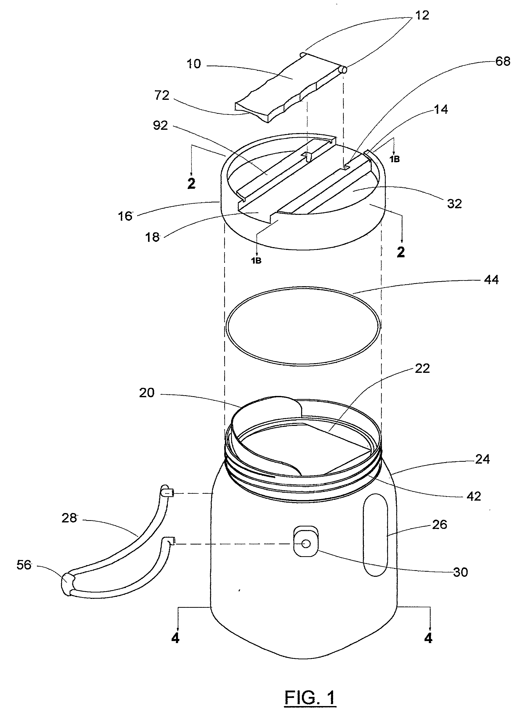
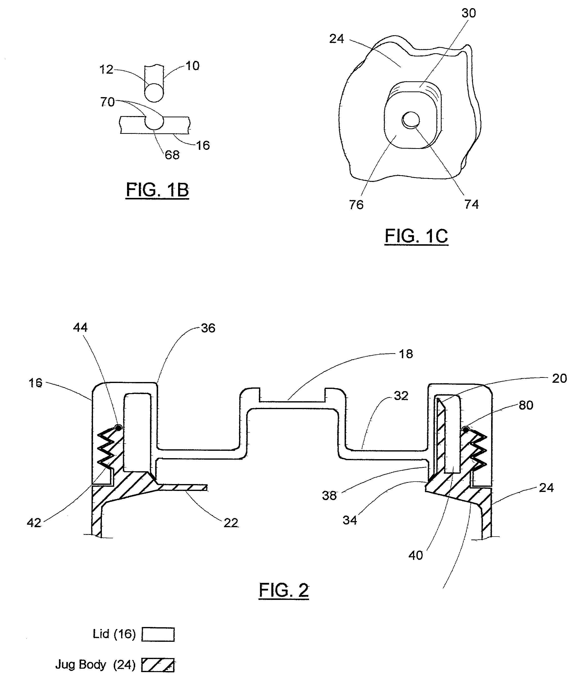
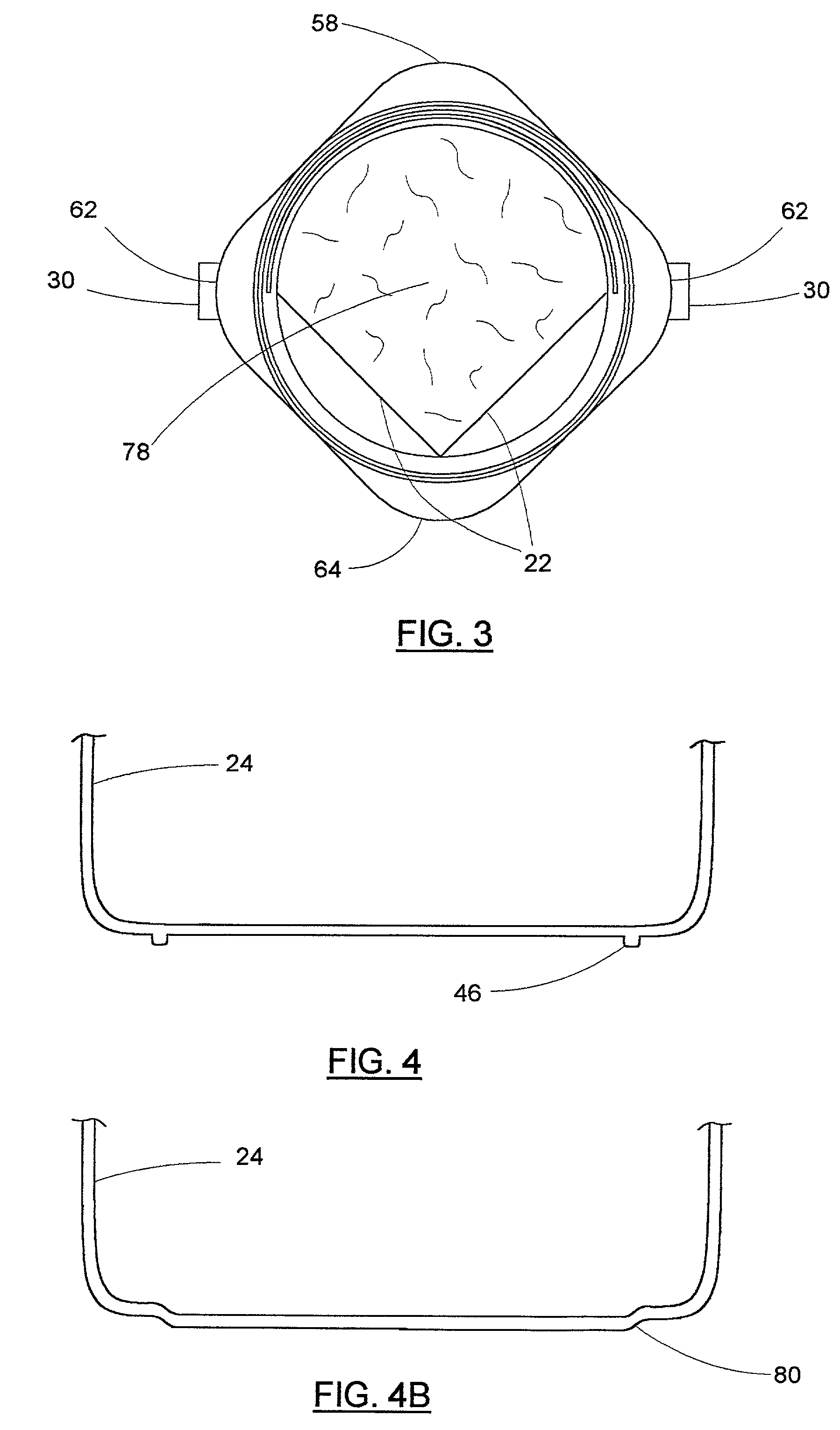
[0045] A preferred embodiment of the present invention is illustrated in FIG. 1 in exploded part format. The container has a jug-like body 24, preferably of one-piece plastic construction The jug body may be blow-molded and made of high-density polyethylene (HDPE), and can be made resistant to oil-based materials and the like by treating the interior with a process such as fluorination. It has a plastic screw-type lid 16, a flip handle 10 with two cylindrical, mounting hinge pins 12 protruding from its sides on one end. Both the lid and flip handle can be made of commonly available strong, plastic materials such as HDPE, ABS or PVC. Both can be injection molded or fabricated from stock. The preferred embodiment of the container also has a rigid swing handle 28 externally mounted onto the body at its ends, and an optional swing handle grasp pad 56 which fits around the middle of the swing handle The swing handle is made of strong, corrosion-resistant metal such as aluminum or stainle...


PUM


Abstract

An improved container for storing, dispensing and handling viscous and semi-viscous fluids such as paint and the like, having novel spout and other design features that enable substantially dripless dispensing and improved handling and storage

Description

[0001] The present invention relates to containers for viscous and other fluids and to improvements in the containment, dispensing and handling of the fluids, being more particularly, though not exclusively, concerned with architectural coatings such as paints and the like and to significant improvement in current paint can design.[0002] Nearly all one-gallon and smaller containers of paint are sold in cylindrical metal cans having an upper edge with a groove that accepts the annular protrusion of a high friction metal lid secured by a press fit. This arrangement has many operational drawbacks that the industry has put up with for many decades These include the lack of a locking mechanism that would prevent the friction lid, popping off if the can is dropped from a height as little as one meter, with consequent spilling of the contents widely on the ground. The lid, moreover, must be pried off with a tool to gain access to the paint, which proves a problem if no tool is available. T...

Claims


Application Information

Patent Timeline
IPC IPC(8): B44D3/12B65D25/28B65D25/32B65D25/42B65D43/02
CPCB44D3/127B44D3/128B65D23/104B65D23/108B65D25/2876B65D25/32B65D25/42B65D43/0231B65D2543/00092B65D2543/00296B65D2543/005B65D2543/00537B65D2543/00555B65D2543/0087B65D2543/00972B65D2543/0099
Inventor BRAVO, MICHAEL H.ROWLES, CRAIG M.SULLIVAN, JOHN P.MARKHAM, DAVIDSCOTT, MARK W.VAN BUITEN, CHRISMASCOLI, GREGORY J.SLACK, ROBERTLEE, CORINNA
Owner THE SHERWIN-WILLIAMS CO
Learn More