Method and apparatus to exercise developmentally delayed, physically and/or neurologically impaired persons

a technology for developing disabled children and physical and/or neurologically impaired persons, applied in non-surgical orthopedic devices, walking aids, physical therapy, etc., can solve the problems of restricting the transition into alternative postures, restricting the promotion of weight bearing activities, and restricting the transition to alternative postures. , to achieve the effect of gaining the strength necessary

Inactive Publication Date: 2001-10-04
COMMUNITY PRODS
View PDF0 Cites 53 Cited by
  • Summary
  • Abstract
  • Description
  • Claims
  • Application Information

AI Technical Summary

Benefits of technology

0014] It is therefore an object of the present invention to help developmentally delayed, physically and/or neurologically impaired ...

Problems solved by technology

These devices limit the developmentally disabled child to just the creeping position, thereby restricting transition into alternative postures.
However, Campbell '114 does not promote quadruped, weight bearing activities.
These devices also prevent the child from de...

Method used


Image

  • Method and apparatus to exercise developmentally delayed, physically and/or neurologically impaired persons
  • Method and apparatus to exercise developmentally delayed, physically and/or neurologically impaired persons
  • Method and apparatus to exercise developmentally delayed, physically and/or neurologically impaired persons

Examples


embodiment 401

[0150] FIG. 16 shows a wall-mounted support frame embodiment 401 of the present invention having a support trolley 408 having a pair of rails 407 similar to the structures shown in FIGS. 12 and 13. In FIG. 16 support trolley 408 rolls along rails 407 by means of trolley wheels 406. Support trolley 408 is in turn attached to downwardly extending support extension 409 by height adjustment collar 421 with height adjustment pin 422 fixing support trolley 408 in position relative to support extension 409. A pair of stop plates 426 at either end of rails 407 serve to arrest the motion of support trolley 408 at the respective ends of its travel and stop plates 426 also serve as wall mounting brackets. Rail braces 486 maintain rails 407 in spaced apart position relative to each other.

[0151] Frame hanger 410 extends outwardly from its attachment at the bottom of support extension 409. Frame hanger 410 has a plurality strap restraints 412 downwardly extending therefrom, which strap restraints...

embodiment 501

[0152] FIG. 17 shows a ceiling-mounted support frame embodiment 501 of the present invention having a support trolley 508 having a pair of rails 507 similar to the structures shown in FIGS. 12 and 13. In FIG. 17 support trolley 508 rolls along rails 507 by means of trolley wheels 506 [not shown]. Support trolley 508 is in turn attached to downwardly extending support extension 509 by height adjustment collar 521 with height adjustment pin 522 fixing support trolley 508 in position relative to support extension 509. A pair of stop plates 526 at either end of rails 507 serve to arrest the motion of support trolley 508 at the respective ends of its travel and stop plates 526 also serve as ceiling mounting brackets. Rail braces 586 maintain rails 507 in spaced apart position relative to each other.

[0153] Frame hanger 510 is shown as a disk but may be a frame as shown in FIG. 16. As shown in FIG. 17, disk hanger 510 extends outwardly from its attachment at the bottom of support extension...

embodiment 801

[0156] FIG. 20 shows hand-held frame support embodiment 801 having a graspable bar supporting a pair of hand-held strap loop handles 872 from which a plurality of straps 871 extend downwardly therefrom. Straps 871 in turn attach to strap restraints 812 on body suit 860, so as to position a child 870 with desirable support for therapy. At least one strap restrain 812 on body suit 860 is attached in the area of the hips of child 870 so as to position a child 770 with desirable support for crawling and creeping.

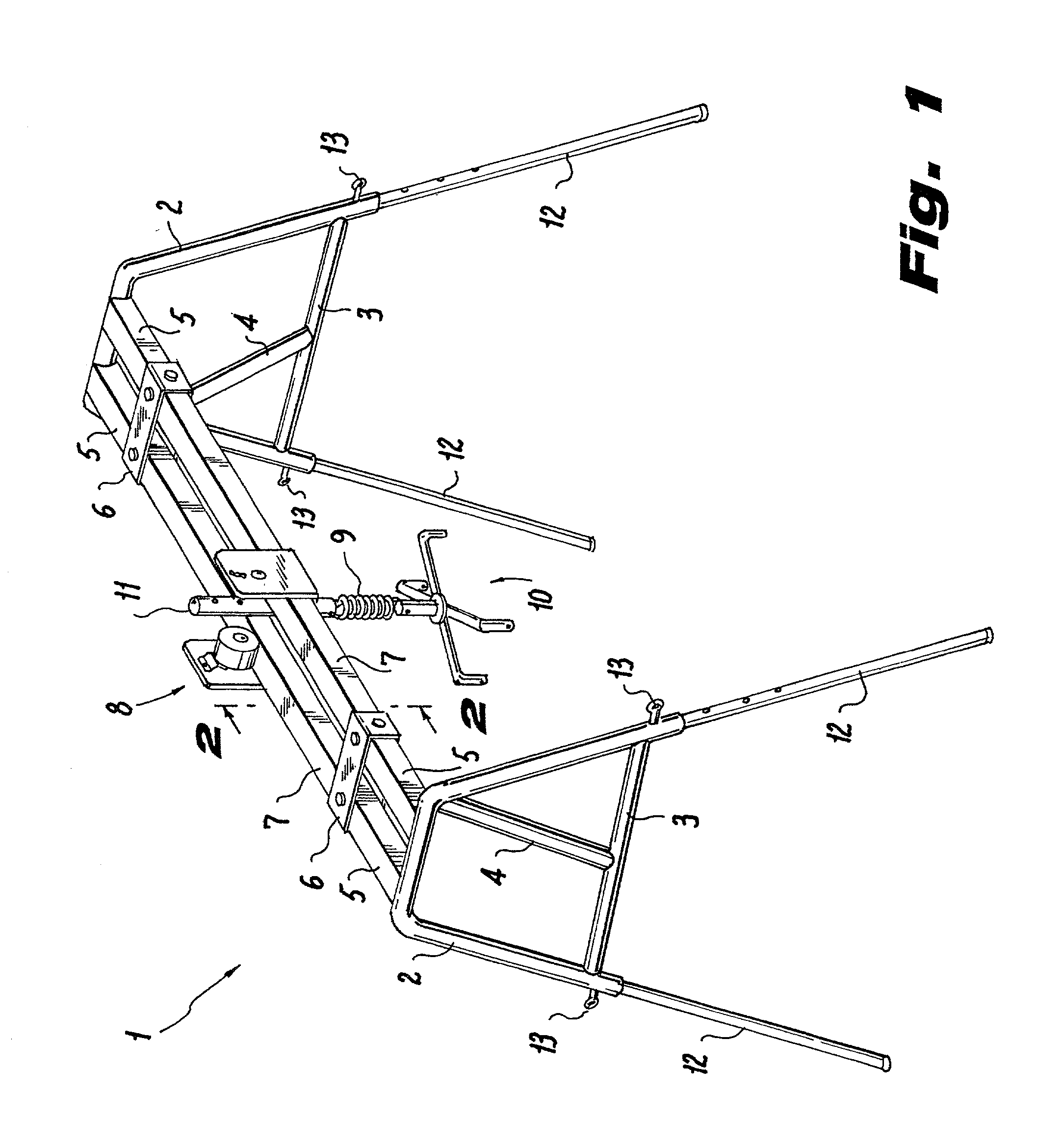
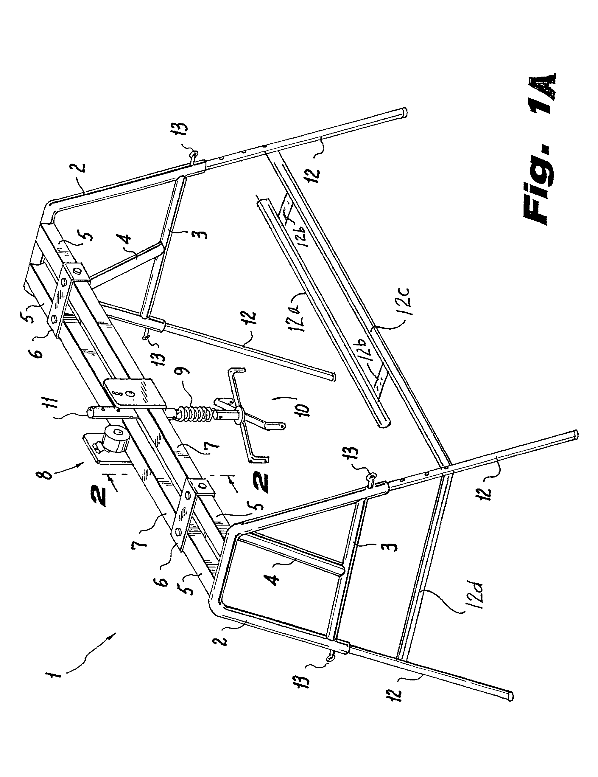
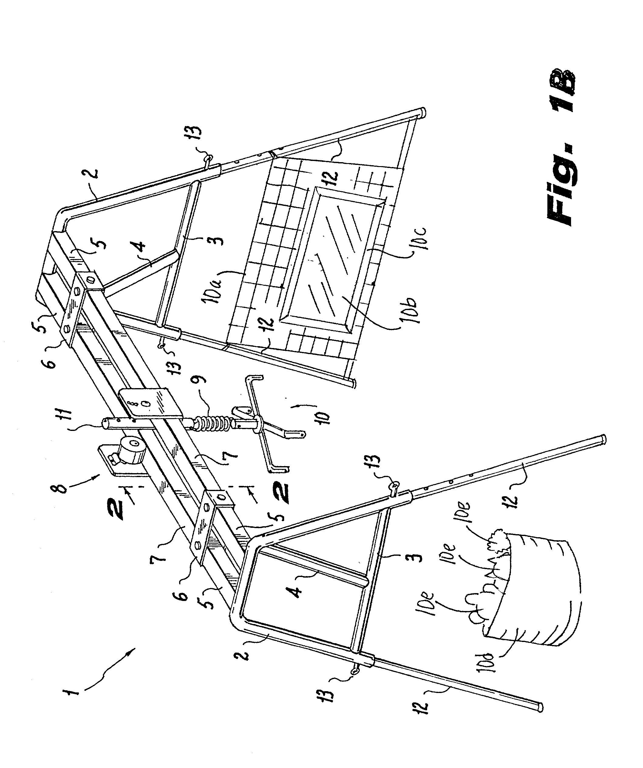
[0157] FIG. 21 shows a kit 900 for a support frame embodiment with convenient packaging including receptacle 903 for support frame members, as well as visually attractive target members, such as mirror 905 or activity net 929 to hold toys. Lit 900 also optionally includes disk hanger 910, straps 971, body suit 960 or toy box 927. Mirror 905 is preferably a safety mirror with soft edges can be placed beyond one set of legs of a frame, such as legs 12 of frame 1 shown in FIG. 1, t...


PUM


Abstract

An exercise assistive device to help a developmentally developed person, or a physically or neurologically impaired person, such as a child or adult, develop vestibular balance and muscle control, so that the person can learn to perform mobility activities, such as crawling, sitting upright, standing or walking. The device includes a support frame supporting a body suit that is moved longitudinally, and optionally transversely and rotationally. The body suit may be optionally spinally supported. The body suit is optionally suspended from either a hand-held frame, like a marionette, or from a floor-mounted, wall-mounted or ceiling mounted frame with a glidable support dolly. Flexible connector straps are provided between the body suit and body suit glidable support dolly and made of a material such as reinforced fabric, elastic or canvas. These connector straps are positioned in spaced-apart relation to one another about the body suit. The body suit is suspended from the seat-support leg by the connector straps that extend between the body suit and fasteners. The fasteners upon the body suit are strategically placed to assist the person assume various postural positions ranging from the upright sitting or standing position, such as at the shoulders, to oblique or horizontal crawling quadruped positions. The person may be encouraged to travel forward, backward or sideways by sensory attractive items, such as mirrors, toys, netting arrays or pull bars.

Description

[0001] This application is a continuation-in-part of application Ser. No. 09 / 676,674, filed Oct. 2, 2000, which application is a continuation-in-part of provisional application Ser. No. 60 / 196,261 filed Apr. 11, 2000, which application is a continuation-in-part of application Ser. No. 09 / 412,189 filed Oct. 5, 1999. This application is also a continuation-in-part of application Ser. No. 09 / 602,700 filed Jun. 24, 2000, which application is a division of application Ser. No. 09 / 412,189 filed October 5, 1999.[0002] The subject matter of the aforementioned patent applications is incorporated by reference herein.[0003] The present invention relates to methods and devices to promote ambulation in developmentally disabled persons, especially children, as well as physically and neurologically impaired persons.[0004] The invention relates to a method and apparatus used to help developmentally delayed, physically and / or neurologically impaired persons, such as children or adults, exercise spec...

Claims


Application Information

Patent Timeline
IPC IPC(8): A47D13/04A47D13/08A61H3/00
CPCA47D13/046A61H3/008A61H2201/0192A61H2201/1607A61H2201/1611A61H2201/1616A61H2201/1621A61H2201/163A61H2201/1642A61H2201/165
Inventor BINGHAM, ANNE
Owner COMMUNITY PRODS
Why Eureka
Try Eureka