
Processing center comprising a hot-stamping machine, hot-stamping machine and processing center comprising a special storage magazine for such a hot-stamping machine

a technology of hot stamping machine and processing center, which is applied in the direction of rotary presses, printing, stereotype printing, etc., can solve the problems of damage to the rubber surface, unsatisfactory thruput of such units, and inability to use hot stamping on straight workpieces

Inactive Publication Date: 2001-10-25
HOMAG MASCHBAUU
View PDF0 Cites 6 Cited by
  • Summary
  • Abstract
  • Description
  • Claims
  • Application Information

AI Technical Summary

Benefits of technology

[0011] The gist of the invention is instead of moving the workpiece, as known in prior art, to maintain the workpiece stationary and to guide the means needed for hot transfer finishing along the contour to be coated or about the surface area of the workpiece. This now makes it possible to process also largish workpieces due to the novel idea of guiding the means for implementing hot transfer finishing about the workpiece. In addition, there is now no problem in automatically tracing any kind of curved contour. On top of this, several workpieces secured to a workbench can now be processed by a plurality of hot transfer finish assemblies each moveable separately.
[0027] An embodiment is also conceivable in which a joint is provided in the hot transfer finish assembly permitting swivelling of the complete hot transfer finish assembly relative to a support serving insertion in the spindle unit of the machining center. Optimally this swivelling of the hot transfer finish assembly about the joint can be implemented by means of an electric motor to thus make it possible, for instance, to coat both vertical and horizontal surface areas with the lacquer or transfer coating in hot transfer finishing. In addition to this, this would also make inclined surface areas coatable by means of a special embodiment of a hot transfer finish assembly in accordance with the invention.

Problems solved by technology

When done on the fly, hot finishing can only be put to use on straight workpieces, whereas where workpieces having curved contours are concerned stationary machines are used.
This is why these bench devices can be put to use only for relatively small workpieces to be coated, since larger parts are too difficult to handle.
This is why the thruput achievable with such units is unsatisfactory.
In addition, since the transfer drum is motor-powered it can be continued to be rotated even when an emergency OFF is instigated, despite the heating still radiating, which could otherwise result in damage to the rubber surface of the transfer drum were it not rotating.
One technically uncomplicated and cost-effective solution consists of the transfer drum being power shiftable from the waiting position into the working position and vice-versa.

Method used


Image

  • Processing center comprising a hot-stamping machine, hot-stamping machine and processing center comprising a special storage magazine for such a hot-stamping machine
  • Processing center comprising a hot-stamping machine, hot-stamping machine and processing center comprising a special storage magazine for such a hot-stamping machine

Examples


Embodiment Construction

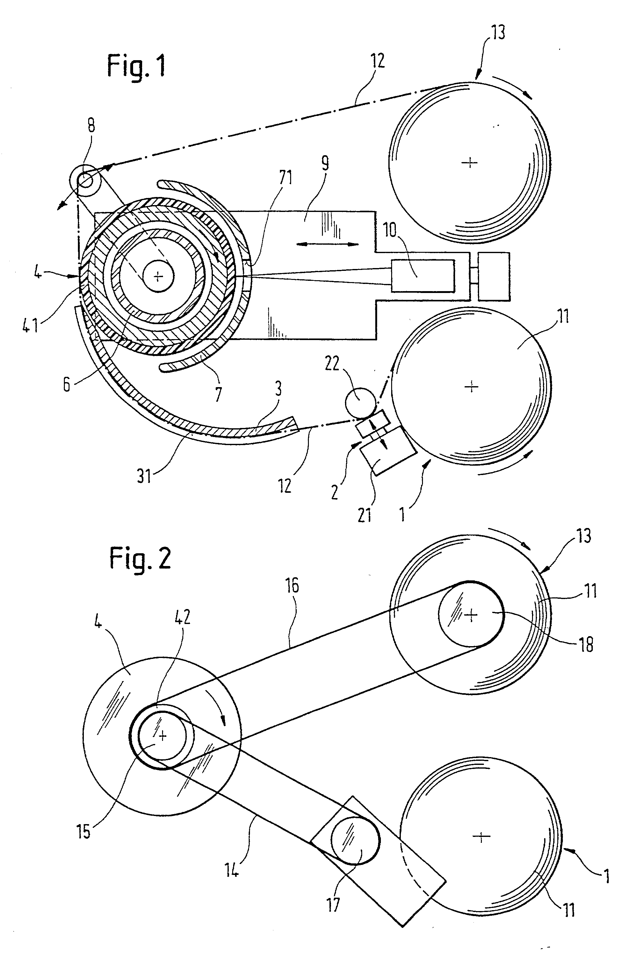
[0033] Referring now to FIG. 1 there is illustrated a diagrammatic plan view of the individual components and their relation to each other of a hot transfer finish assembly in accordance with the invention. A supply reel 1 comprises a non-powered film plate serving to mount the roll of film 11 which in this case com prises a reeled backing film 12 with the lacquer or transfer coating provided thereon to be applied to a workpiece contour.

[0034] Provided downstream of the supply reel 1 is a braking means 2 comprising a deflector pulley 22 and opposite the deflector pulley 22 an air or motor actuated shiftable brake block 21. Guided between the deflector pulley 22 and the brake block 21 is the backing film 12 with the lacquer or transfer coating provided thereon.

[0035] The braking means 2 is followed by a film guide 3 comprising a curved outer surface area 31 along which the backing film 12 with the lacquer or transfer coating provided thereon glides in being advanced to a transfer dru...


PUM

PropertyMeasurementUnit
thickaaaaaaaaaa
surface areaaaaaaaaaaa
circumferenceaaaaaaaaaa

Abstract

A processing center is disclosed that comprises at least one support capable of displacement in the X and Y axes, and preferably also in the Z axis, and at least one hot-stamping machine for applying a paint layer or a transfer layer, which is located on a support film, onto the surface of a workpiece and mainly onto the curved outline of a plate-shaped workpiece. The hot-stamping machine comprises an unwinding unit for unwinding the support film supporting the paint or transfer layer, a take-up unit for taking up the support film used, and at least one stamping cylinder which is rotationally mounted between the unwinding unit and the take-up unit and which can be applied onto the workpiece. The stamping cylinder is used for transferring the paint or transfer layer from the support film onto the workpiece.

Description

[0001] The invention relates to a processing or machining center including at least one support moveable in the X, Y and to advantage also in the Z direction for supporting a hot transfer finish assembly for applying a lacquer or transfer coating provided on a backing film to a workpiece surface area, more particularly to a curved workpiece contour of a sheet workpiece. The invention relates furthermore to one such hot transfer finish assembly specially devised to be interchangeable in a spindle unit of a machining unit, more particularly a machining center.[0002] The invention relates furthermore to a machining center including a spindle unit moveable in the X, Y and Z direction for mounting tools and assemblies for machining wood or plastics or the like which is equipped with a special storage magazine for locating one or more hot transfer finish assemblies.PRIOR ART[0003] In hot transfer finishing the work is done in general with a backing film on which a lacquer or transfer coat...

Claims


Application Information

Patent Timeline
Patent Type & Authority Applications(United States)
IPC IPC(8): B41F16/00
CPCB41F16/00
Inventor FRITZ, MARKUSKALMBACH, KURTSCHMID, JOHANNES
Owner HOMAG MASCHBAUU
Learn More