Method and apparatus for near lossless digital image compression

a digital image and compression algorithm technology, applied in image data processing, instruments, computing, etc., can solve problems such as destruction of motion appearance, insufficient usb data rate to support a frame rate of 15 fps, and inconvenient interframe compression

Inactive Publication Date: 2001-11-15
INTEL CORP
View PDF5 Cites 6 Cited by
  • Summary
  • Abstract
  • Description
  • Claims
  • Application Information

AI Technical Summary

Problems solved by technology

In general, greater frame rates contribute to heightened appearances of motion, while lower frame rates contribute to the observer being able to perceive individual frames, thus destroying the appearance of motion.
However, the USB data rate of 8 Mbits / second is insufficient to support a frame rate of 15 fps for 320.times.240 video.
Interframe compression is not ideally suited to the USB environment.
This is due to the fact that the USB architecture will not guarantee that every frame of digital video data will be transferred.
Video compression techniques that humans perceive as "lossy" do not fully preserve all the information originally captured in an image.
In general, for "lossy" techniques, as the compression of the video data is increased, the quality of the video suffers.

Method used


Image

  • Method and apparatus for near lossless digital image compression
  • Method and apparatus for near lossless digital image compression
  • Method and apparatus for near lossless digital image compression

Examples


Embodiment Construction

[0028] For this embodiment, each picture element has a luminance intensity component (the Y component) and two color components (the C.sub.R and C.sub.B components). The totality of Y components for a given frame is referred to as the Y plane for that frame. Likewise, the totality of the C.sub.R and C.sub.B components for a given frame can be referred to as C.sub.R and C.sub.B planes, respectively. These luminance and color components conform to the International Telecommunications Union--Radio Sector (ITU-R) BT.601 standard. Other video color systems, such as RGB, may also be used with the invention.

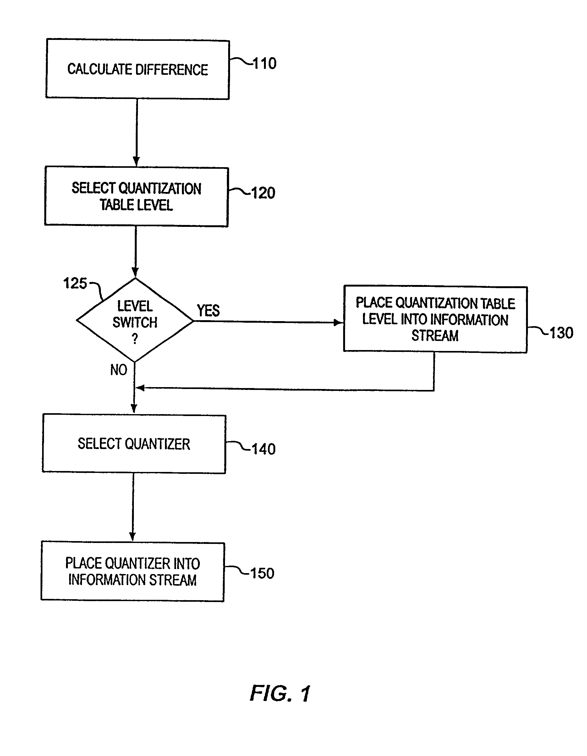
[0029] FIG. 1 shows a flow chart of a method for encoding data representing a component of a picture element implemented in accordance with one embodiment of the invention. At step 110, a difference is calculated between a sample value for a picture element from a current scan line and a sample value for a picture element from a previous scan line.

[0030] Following step 110, a quantizati...


PUM


Abstract

A method and apparatus for encoding a digital image is disclosed. A difference is calculated between a first sample from a current scan line and a corresponding second sample from a previous scan line. A quantization table level is selected from a quantization table that includes at least one level, and information identifying the selected level is placed into an information stream. A quantizer is selected from the quantization table level based on the calculated difference and information corresponding to the selected quantizer is place into the information stream.

Description

[0001] 1. Field of the Invention[0002] The present invention pertains to the field of digital image compression. More particularly, this invention pertains to algorithms for near-lossless digital video compression.[0003] 2. Background of the Related Art[0004] A video signal comprises a sequence of frames or images which when displayed at a given frame rate (e.g., 15 to 30 frames per second) simulates the appearance of motion to a human observer. Each frame of the video image comprises a matrix of picture elements, known as "pixels" or "pels." A pixel is the minimum unit of the picture which may be assigned a luminance intensity and a color. In a computer, depending on the data format used, as many as 3 bytes of data can be used to define visual information for a pixel. One popular data format assigns a luminance intensity represented by 1 byte of data to each pixel and further assigns a color represented by 2 bytes of data to groups of 4 pixels each. This format results in an averag...

Claims


Application Information

Patent Timeline
Patent Type & Authority Applications(United States)
IPC IPC(8): G06T9/00
CPCG06T9/005
Inventor GOLDSTEIN, JUDITH A.FREYTAG, LAWRENCE K.KEITH, MICHAEL
Owner INTEL CORP
Why Eureka
Try Eureka