Hydraulic antivibration sleeve

Inactive Publication Date: 2002-02-21
HUTCHINSON SA
View PDF0 Cites 22 Cited by
  • Summary
  • Abstract
  • Description
  • Claims
  • Application Information

AI Technical Summary

Benefits of technology

0020] In contrast, when the static load lies in the second range of values, only the first working chamber is influenced by the relative vibratory motion between the two strength members of the sleeve, such that the transfers of liquid take

Problems solved by technology

Unfortunately, in some cases, it can be useful for the antivibration sleeve to opera

Method used


Image

  • Hydraulic antivibration sleeve
  • Hydraulic antivibration sleeve
  • Hydraulic antivibration sleeve

Examples


Embodiment Construction

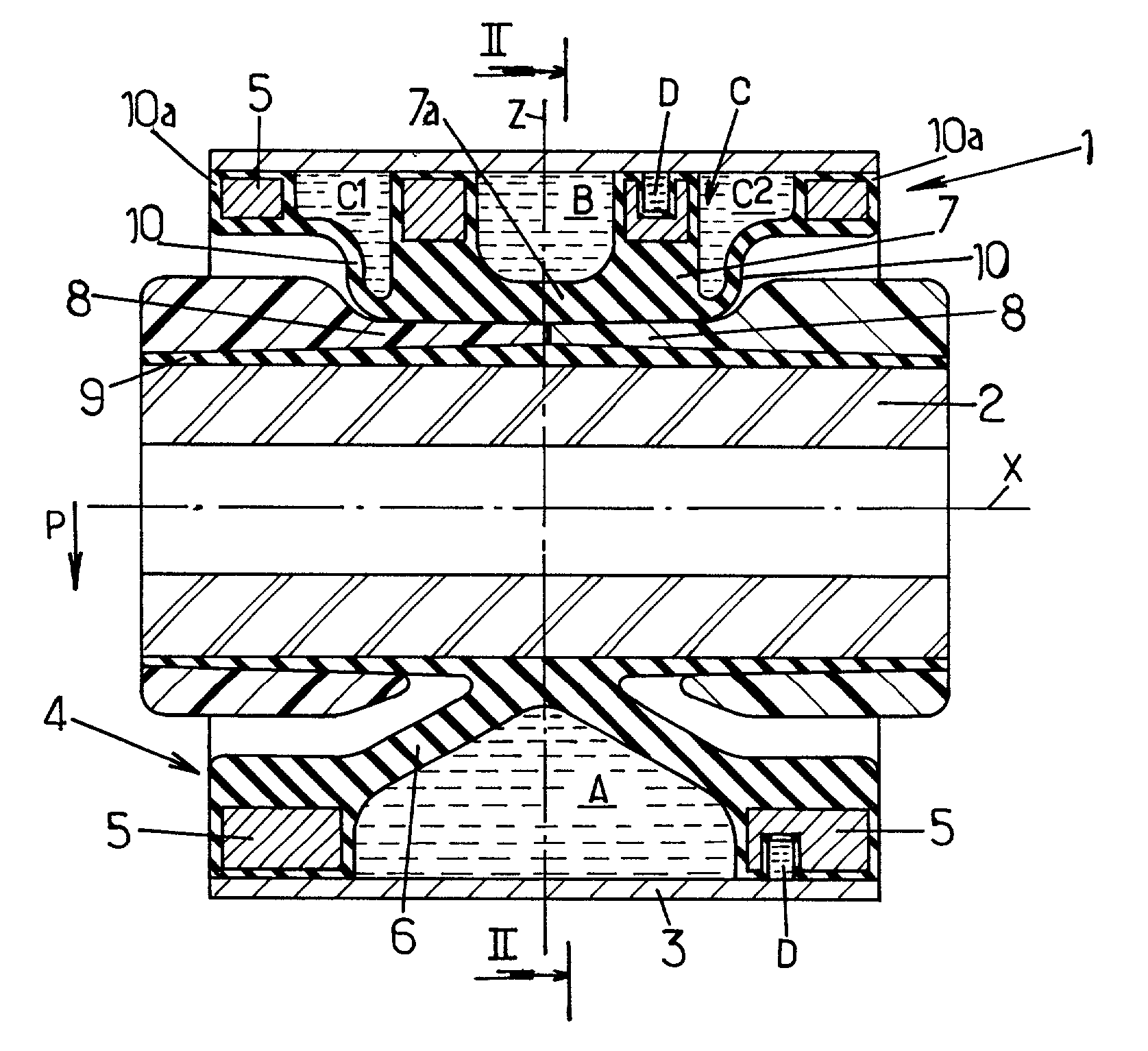
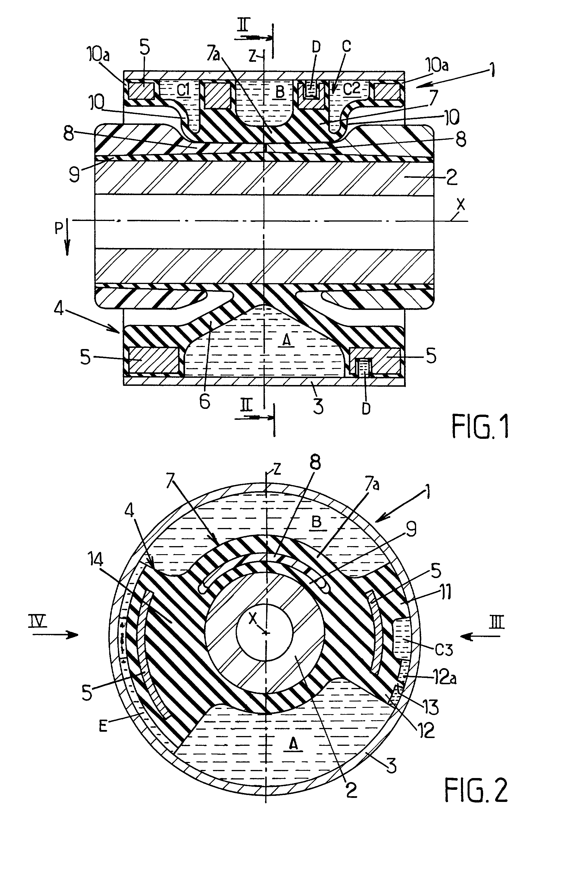
[0039] FIGS. 1 and 2 show a hydraulic antivibration sleeve 1 comprising a rigid inner strength member 2 generally made of metal and extending longitudinally along a central axis X between two axial ends of the sleeve.

[0040] This inner strength member is surrounded by a cylindrical strength member 3 likewise made of metal and extending longitudinally along the axis X, surrounding said inner strength member.

[0041] The strength members 2 and 3 are interconnected by an elastomer body 4 which is overmolded and bonded onto the inner strength member 2 and which includes at its outer periphery a rigid perforated cage 5 generally made of metal and suitable for providing a tight fit between the elastomer body 5 and the outer strength member 3 (where clamping between the periphery of the elastomer body and the outer strength member can be obtained in particular by inserting the elastomer body into the outer strength member and swaging the strength member).

[0042] The elastomer body 4 interconne...


PUM


Abstract

A hydraulic antivibration sleeve comprising two constrictive strength members interconnected by an elastomer body which defines first and second diametrically opposite working chambers and a side compensation chamber. The two working chambers communicate with each other via a constricted passage, while the compensation chamber communicates with the first working chamber only via another constricted passage. The elastomer wall which defines the second working chamber is free and is not in contact with the inner strength member except in a certain range of values for the radial static load supported by the sleeve: this provides two different modes of operation depending on the value of said static load.

Description

[0001] The present invention relates to hydraulic antivibration sleeves.[0002] More particularly, the invention relates to a hydraulic antivibration sleeve comprising:[0003] a rigid inner strength member extending longitudinally along a central axis between two axial ends;[0004] an annular rigid outer strength member which surrounds the inner strength member;[0005] an elastomer body interconnecting the inner and outer strength members, said elastomer body comprising:[0006] a first thick elastomer wall adapted to support a permanent load of value lying in a certain operating domain and applied between the inner and outer strength members parallel to a main vibration direction perpendicular to said central axis, said first thick elastomer wall presenting a central portion secured to the inner strength member and a peripheral portion secured to the outer strength member, thereby defining part of a first liquid-filled working chamber; and[0007] a second thick elastomer wall having a per...

Claims


Application Information

Patent Timeline
IPC IPC(8): F16F13/14F16F13/18
CPCF16F13/1418F16F13/18
Inventor BOUHIER, BERNARDSEIBERT-SANDT, FREDERIC
Owner HUTCHINSON SA
Why Eureka
Try Eureka