Rigid ankle and foot orthosis

a rigid ankle and foot technology, applied in the field of ankle and foot orthosis, can solve the problems of inability to extend over the latero-superior aspect of the talar head, increased joint laxity, and high probability of recurring sprains of injured ankles,

Inactive Publication Date: 2002-03-07
BOWMAN GERALD D
View PDF5 Cites 40 Cited by
  • Summary
  • Abstract
  • Description
  • Claims
  • Application Information

AI Technical Summary

Problems solved by technology

These injured ankles have a high probability of suffering recurring sprains and increased joint laxity.
However, this device fails to extend over the latero-superior aspect of the talar head and therefore lacks s

Method used


Image

  • Rigid ankle and foot orthosis
  • Rigid ankle and foot orthosis
  • Rigid ankle and foot orthosis

Examples


Embodiment Construction

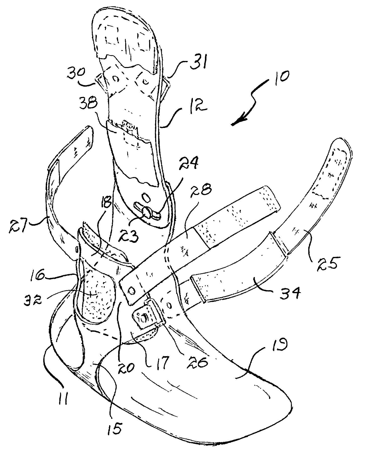
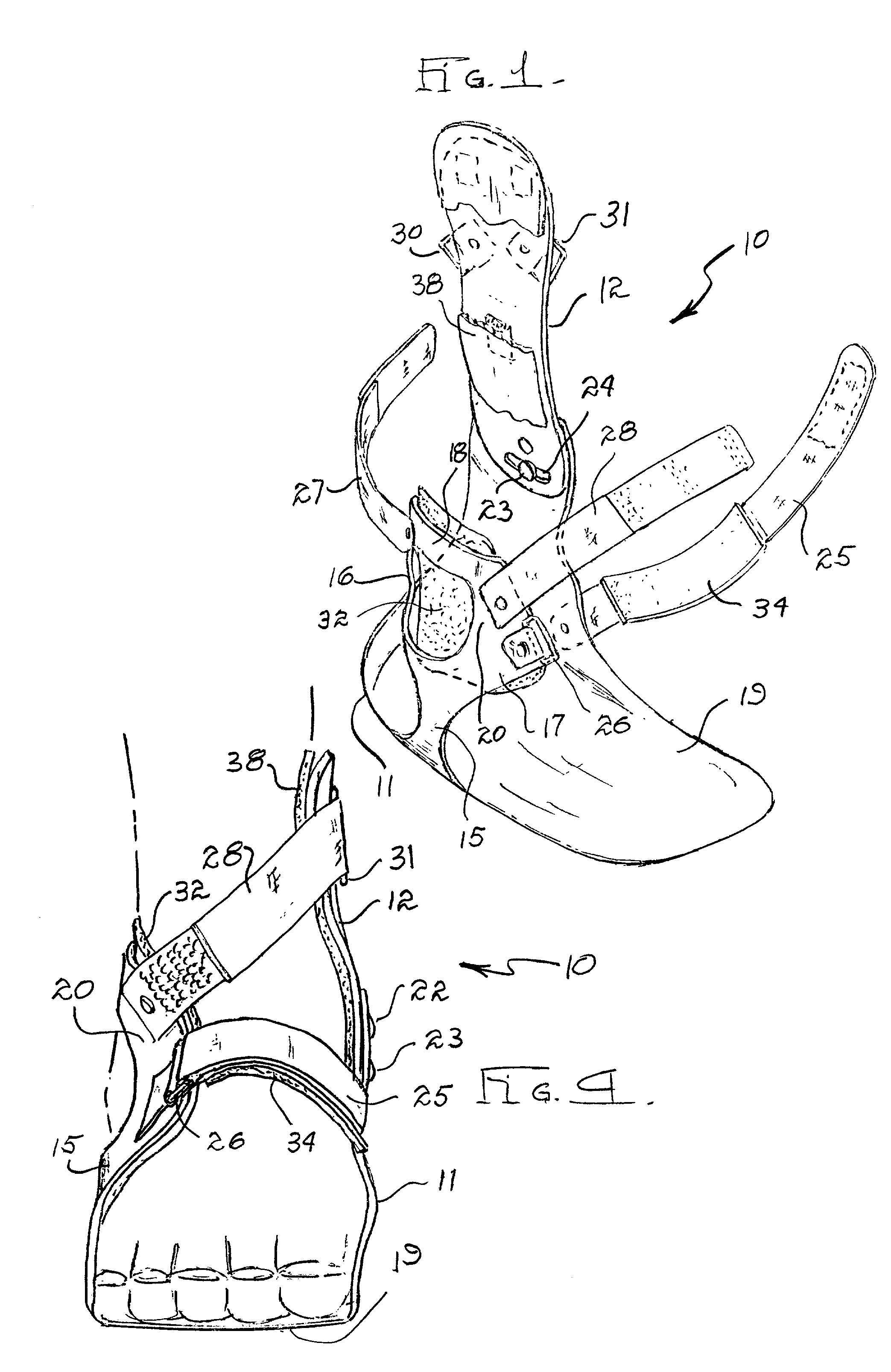
[0020] Referring in detail to FIGS. 1 and 2, the ankle and foot orthosis or brace of the present invention is illustrated in the direction of arrow 10 which includes a medial / plantar / lateral plastic shell 11 and a contoured medial plastic shell 12.

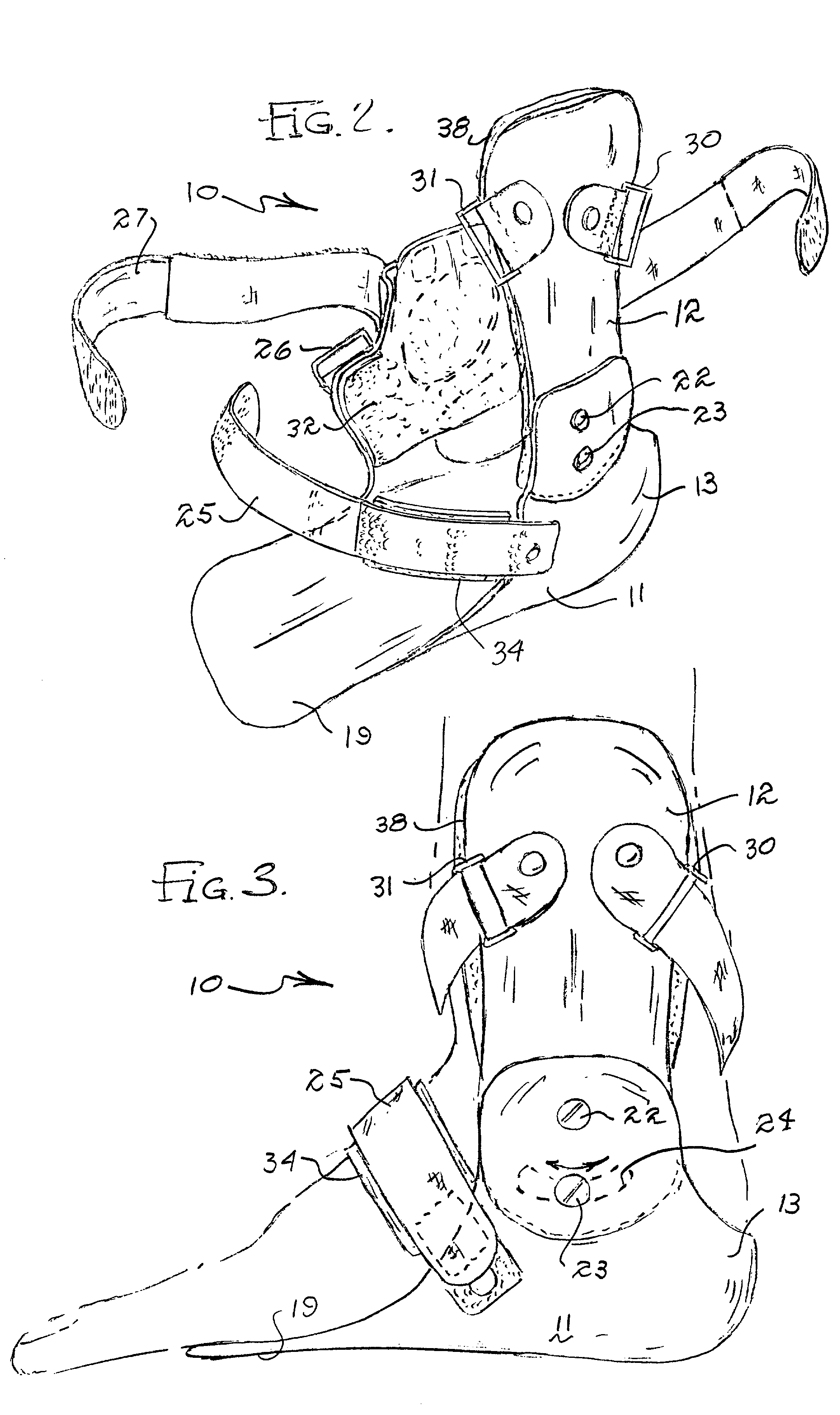
[0021] FIG. 2 illustrates the medial section 13 of the medial / plantar / lateral shell which encompasses the medial calcaneus and extends upwards to encompass the medial malleolus. Its anterior margin lies at the level of the anterior margin of the medial malleolus. Posteriorly it extends upwards at an angle. Just below the medial malleolus it forms a raised area to accommodate the interconnecting medial shell 12. In its raised area it has two small apertures for receiving a pivot screw 22 and a movement limiting screw 23.

[0022] FIG. 2 shows a lateral section of the medial / plantar / lateral shell as it forms a strut 15 extending up out of the footplate 19 in an area approximating the front of the calcaneus to the base of the 5th metatarsal. Jus...


PUM


Abstract

A therapeutic ankle and foot orthosis or brace includes a lower shell and an upper lateral shell which are movably coupled together by a pivot so that the shells accommodate the contour, size and shape of the user's foot and ankle. Cushions are included on the shells to provide comfort and straps with hook and pile fasteners are employed to detachably retain the combined shells on the ankle and foot of the user.

Description

[0001] 1. Field of the Invention[0002] The present invention relates to the field of ankle and foot orthosis and more particularly to rigid ankle and foot orthosis used in athletic and medical applications for individuals who have injured their ankle or have an unstable ankle joint.[0003] 2. Brief Description of the Prior Art[0004] Ankle orthoses and ankle and foot orthoses have become a popular form of treatment for controlling lateral ankle motion in the injured or unstable ankle. Lateral ankle injuries account for the majority of ankle injuries. These injured ankles have a high probability of suffering recurring sprains and increased joint laxity. The ankle joint is an articulation involving the tibia and fibular with the talus. The talus also forms a major articulation with the calcaneus (sub-talor joint). As the ankle joint is very intimately connected to the sub-talor joint in the foot, an ankle and foot orthosis must ideally control lateral ankle motion (inversion) and sub-ta...

Claims


Application Information

Patent Timeline
IPC IPC(8): A61F5/01
CPCA61F5/0127
Inventor BOWMAN, GERALD D.
Owner BOWMAN GERALD D
Why Eureka
Try Eureka