Stopper device and telescopic unit

a technology of stopper device and telescopic unit, which is applied in the direction of rod connection, machine support, manufacturing tools, etc., can solve the problem of another object being inadvertently caught in indentation 5, and achieve the effect of preventing inadvertent catching

Inactive Publication Date: 2002-03-14
VELBON +1
View PDF5 Cites 41 Cited by
  • Summary
  • Abstract
  • Description
  • Claims
  • Application Information

AI Technical Summary

Benefits of technology

0005] It is an object of the present invention is to provide a stopper device and a telescopic unit which are capable of preventing inadvertent catching.

Problems solved by technology

Such a structure presents the possibility of another object getting inadvertently caught in indentation 5.

Method used


Image

  • Stopper device and telescopic unit
  • Stopper device and telescopic unit
  • Stopper device and telescopic unit

Examples


Embodiment Construction

[0031] Referring to FIG. 3, a tripod 11 has a base member 12 with three leg attachments 13, each of which is attached to a telescopic unit 15. Each telescopic unit 15, serving as a leg unit, is attached to the corresponding leg attachment 13 through a horizontal shaft portion 16 so that telescopic unit 15 can swing around shaft portion 16, thereby adjusting its position. An elevator rod 17 is mounted on base member 12 in such a way that the height of elevator rod 17 is adjustable. A panhead (not shown), which may be used with a camera, is removably attached to the top of elevator rod 17.

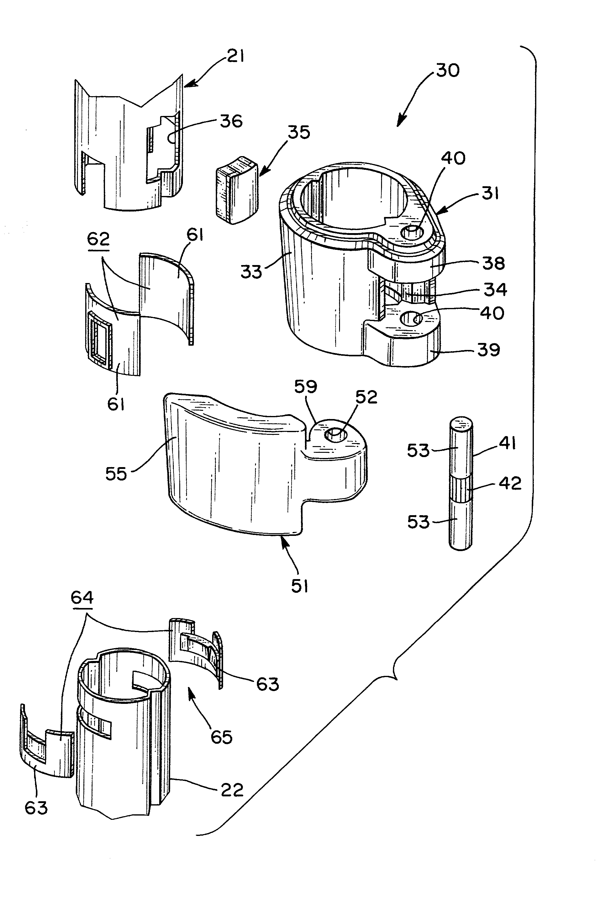
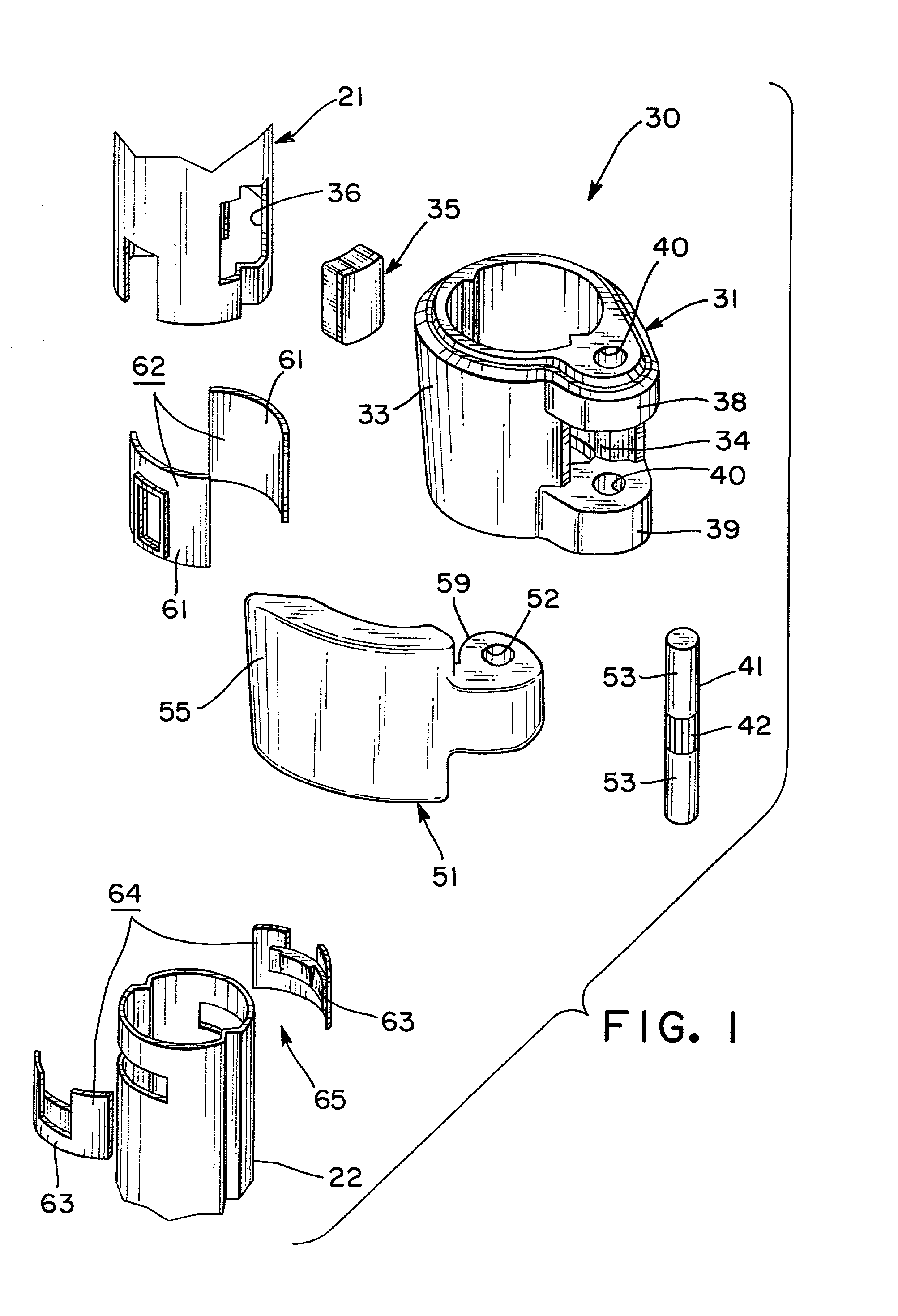
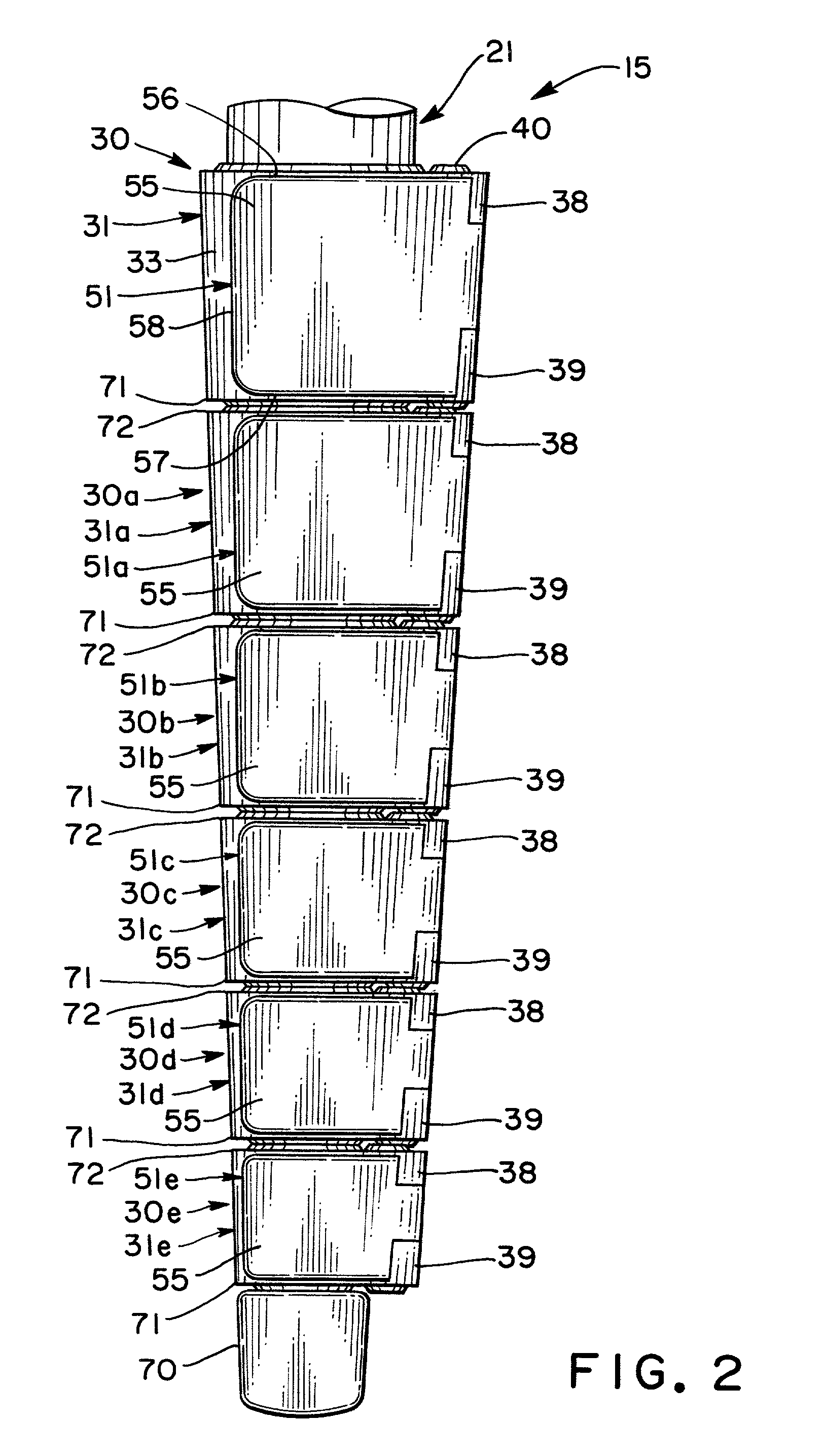
[0032] Each one of the three telescopic units 15 has a leg structure comprised of a plurality of segments, preferably three or more segments. For example, each telescopic unit 15 of one embodiment of the present invention has seven segments having a similar shape, each segment having a circular cross section. The seven segments consist of a first tubular member 21, a second tubular member 22, a third...


PUM


Abstract

A first stopper supporting member (31), supporting a stopper (35) which controls movement of a second tubular member (22) of a telescopic unit (15) along a first tubular member (21), is disposed around the outer surface of the first tubular member (21). A second stopper supporting member (31a), supporting a stopper (35) which controls movement of a third tubular member (23) along the second tubular member (22) is disposed around the outer surface of the second tubular member (22). A facing end (71) of the first stopper supporting member (31) and a facing end (72) of the second stopper supporting member (31a) have nearly the same outer diameter. The resulting telescopic unit (15) is both attractive in appearance and free from the problem of being inadvertently caught by another object.

Description

[0001] The present invention relates to a stopper device for controlling movement of a tubular member along another tubular member. The invention also relates to a telescoping device provided with this stopper device.[0002] Conventional telescopic units of this type include a telescopic unit 1 shown in FIG. 11. A stopper device 2 of telescopic unit 1 has a plurality of tubular members (not shown in the drawing) and generally cylindrical stopper supporting members 3 respectively supporting the stoppers. With respect to the configuration of each stopper, one tubular member is associated with another tubular member in that the other tubular member moves along the one tubular member. Each stopper is adapted to control the movement of the other tubular member. Stopper supporting members 3 are each similar in shape and have dimensions respectively corresponding to the diameters of the tubular members.[0003] Each stopper supporting member 3 is so formed as to extend straight from one of th...

Claims


Application Information

Patent Timeline
Patent Type & Authority Applications(United States)
IPC IPC(8): F16B7/14F16M11/32
CPCF16B7/1454F16M11/32F16M2200/027Y10T403/7071Y10T403/32467Y10T403/7077F16M2200/028
Inventor AKAIKE, MITSURU
Owner VELBON
Why Eureka
Try Eureka