Touch pad, led motion detector head

a motion detector and touch pad technology, applied in the field of infrared motion detectors, can solve the problems of dial or slide switch difficulty in unaided eye, detector mount on open, unprotected walls,

Inactive Publication Date: 2002-03-14
COLEMAN CABLE INC
View PDF0 Cites 7 Cited by
  • Summary
  • Abstract
  • Description
  • Claims
  • Application Information

AI Technical Summary

Benefits of technology

0012] More specifically, the motion detector head that includes a standard, passive-type infrared motion sensor with manually operated controls used to bypass the sensor detector, for basting the range of sensitivity and to program the sensitivity and timer settings. At least two membrane switches are provided that control the motion sensor's "sensitive" and "timer" settings. Connected to the motion sensor's basting and timing circuits are LED lights that illuminate in one of three possible colors to indicate the current sensitivity and timer setting of the motion sensor. The motion detector may also include an optional photocell eye that automatically senses brightness, thereby preventing the sensor from activating the lamps in the daytime.

Problems solved by technology

Unfortunately, some users must mount their detectors on open, unprotected walls.
It is well known that when the detector is mounted under an eave or overhang, the dial or slide switches are difficult to see with an unaided eye.
Even though a detector may be mounted in a protected area, ambient moisture eventually enters the detector through the dial or slide switches causing corrosion

Method used


Image

  • Touch pad, led motion detector head
  • Touch pad, led motion detector head
  • Touch pad, led motion detector head

Examples


Embodiment Construction

)

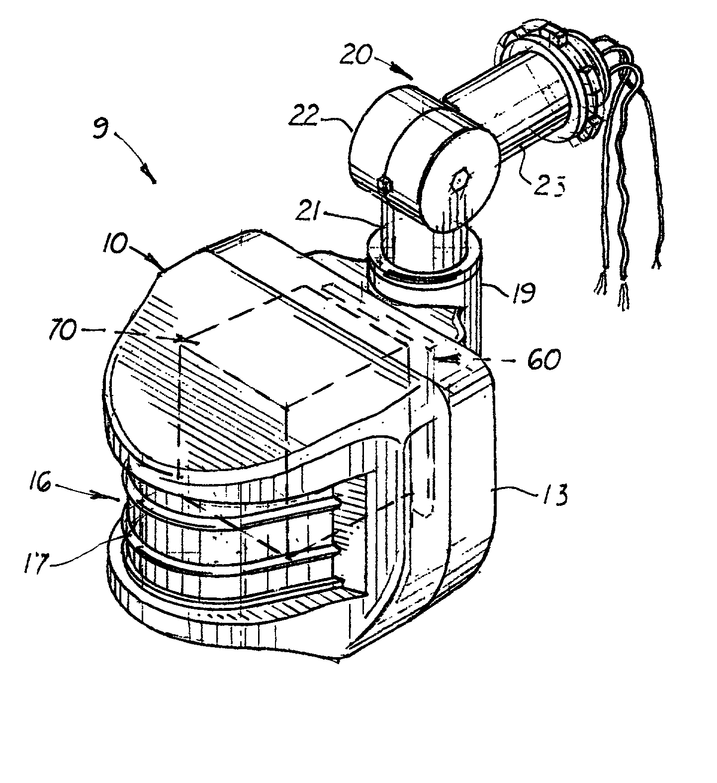
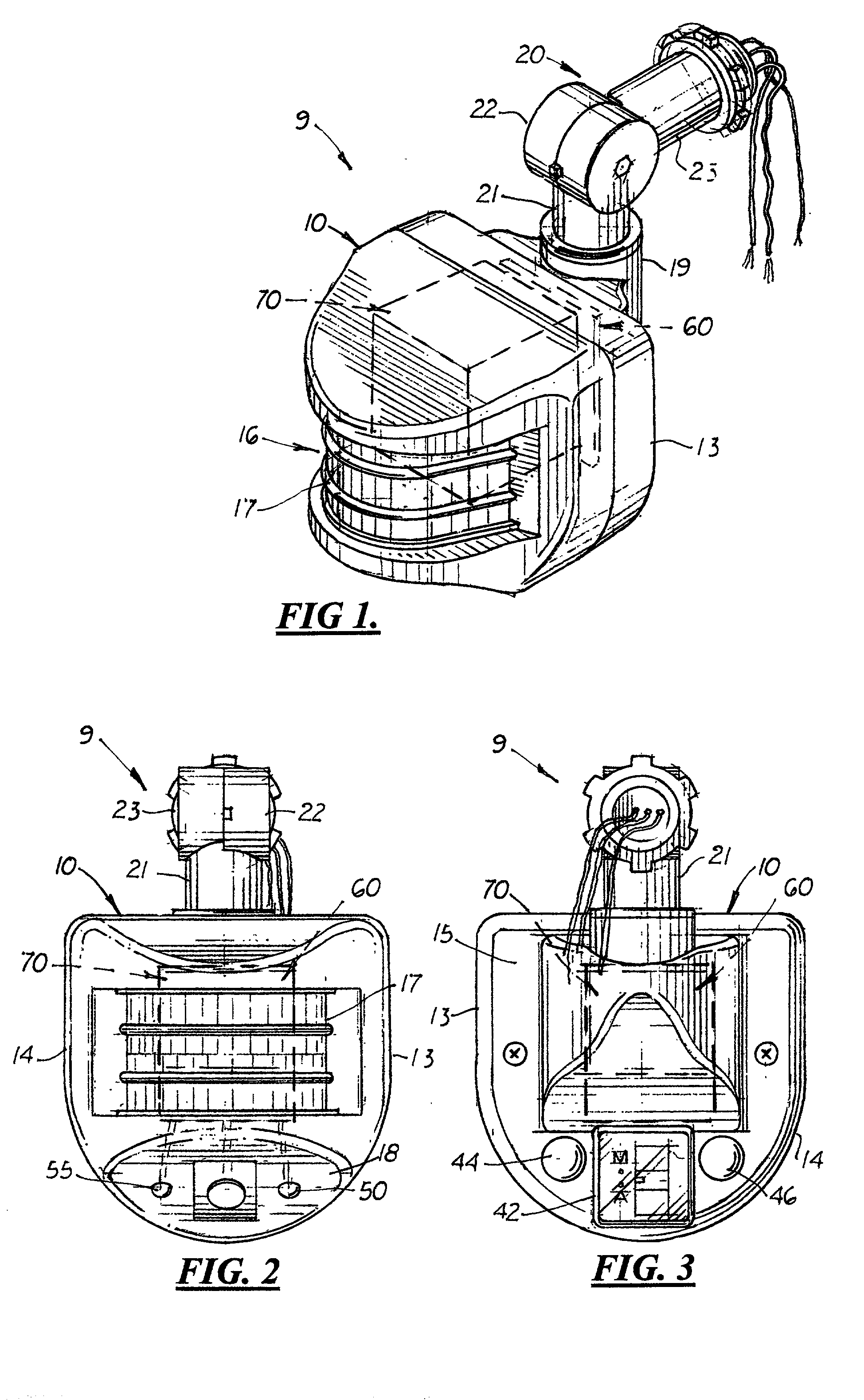
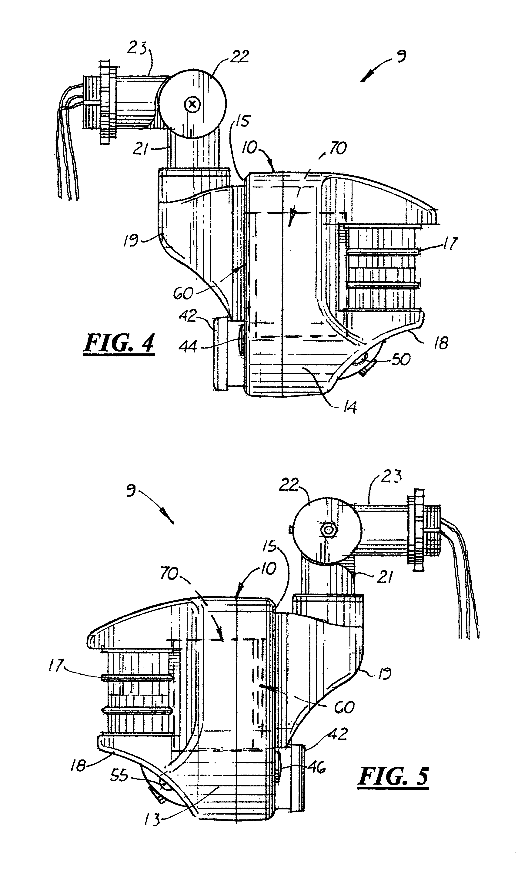
[0021] Referring to the accompanying Figs., there is shown and described an improved motion detector 9 designed to be easier to used and more water resistant. The motion detector 9 includes an outer housing 10 attached to adjustable electrical conduit 20 designed to be attached to a standard electrical box (not shown). The motion detector 9 includes a standard passive, 110-volt motion sensor 70 housed inside the rigid outer housing 10. The motion detector 9 includes a printed circuit board 60 to which a main switch 42 and two touch-activated, membrane style switches 44, 46 and two LED's 50, 55 are attached as discussed further below.

[0022] The outer housing 10 includes a downward curved top surface 11, a bottom surface 12, two side surfaces 13, 14, a rear surface 15, a front opening 16 covered with a partially transparent lens 17, and an upward curved front surface 18. Formed on the upper portion on the back surface 15 is a cylindrical neck 16 designed to connect to a vertically al...


PUM


Abstract

An improved motion detector that includes a passive motion sensor with "test," "sensitivity" and "timer" adjustable functions, mounted inside an outer housing with two water-resistant touch-operated membrane switches used to control these settings. Also mounted on the sides of the outer housing and connected to the motion sensor are at least two bright LED lights designed to illuminate in one of three possible colors to visually indicate the current "test", "sensitivity" or "timer" setting of the motion detector.

Description

[0001] This is a utility patent application based on a provisional patent application (Serial No. 60 / 224,858) filed on Aug. 11, 2000.[0002] 1. Field of the Invention[0003] This invention pertains to infrared motion detectors, and more particularly, to motion detectors with improved time and sensitivity controls for easy use.[0004] 2. Description of the Related Art[0005] Infrared motion detectors typically have three manual controls that enable a user to: (1) test the area of coverage, (2) adjust the length of time the light stays "on" after motion is no longer detected, and; (3) adjust the motion detector infrared sensors' sensitivity to heat and motion. Typically, these controls are dial or slide switches externally mounted on the bottom or back surface of the detector's outer housing.[0006] Many users mount their detectors outdoors under an eave or overhang so that they are is less visible to viewers entering the coverage area. Manufacturers generally prefer that the detector be m...

Claims


Application Information

Patent Timeline
Patent Type & Authority Applications(United States)
IPC IPC(8): G08B13/19G08B29/22
CPCG08B13/19G08B29/22
Inventor LEEN, MONTE A.
Owner COLEMAN CABLE INC
Why Eureka
Try Eureka