Cutting apparatus

a technology of cutting apparatus and cutting edge, which is applied in the direction of forging/pressing/hammering apparatus, metal-working feeding device, handling device, etc., can solve the problems of cutting edge breakage, surface side and rear face depths become non-uniform, and the layer is exfoliated

Inactive Publication Date: 2002-06-13
UHT CORP
View PDF4 Cites 39 Cited by
  • Summary
  • Abstract
  • Description
  • Claims
  • Application Information

AI Technical Summary

Problems solved by technology

When the parallelism is not realized, perfect cutting can not be conducted, edge breakage is caused by colliding the cutting blade with the table, for example, depths of the half cutting from the surface side and rear face become non-uniform.
When half cutting is executed from a position in proximity to the recess portion where a joining area between layers is small, the crack is easily produced at a peripheral wall part of the recessed portion due to dispersion force produced in cracking, a problem of remarkably causing the exfoliation of layer occurs.
Conventionally, as a method of realizing the parallelism, since the parallelism is produced by utilizing jack bolts as mounting members of the inde

Method used


Image

  • Cutting apparatus
  • Cutting apparatus
  • Cutting apparatus

Examples


Embodiment Construction

)

[0072] Next, the present invention will be explained.

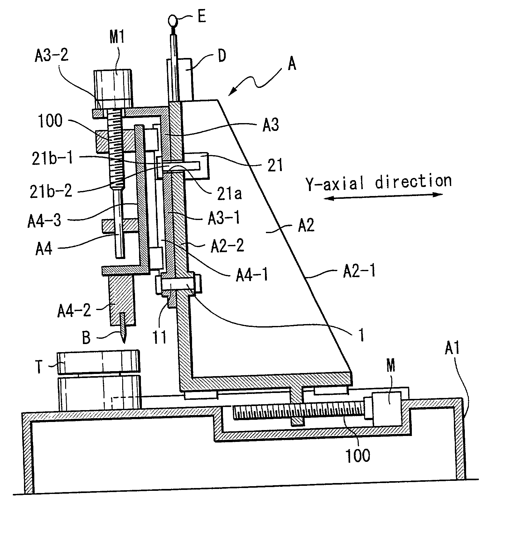
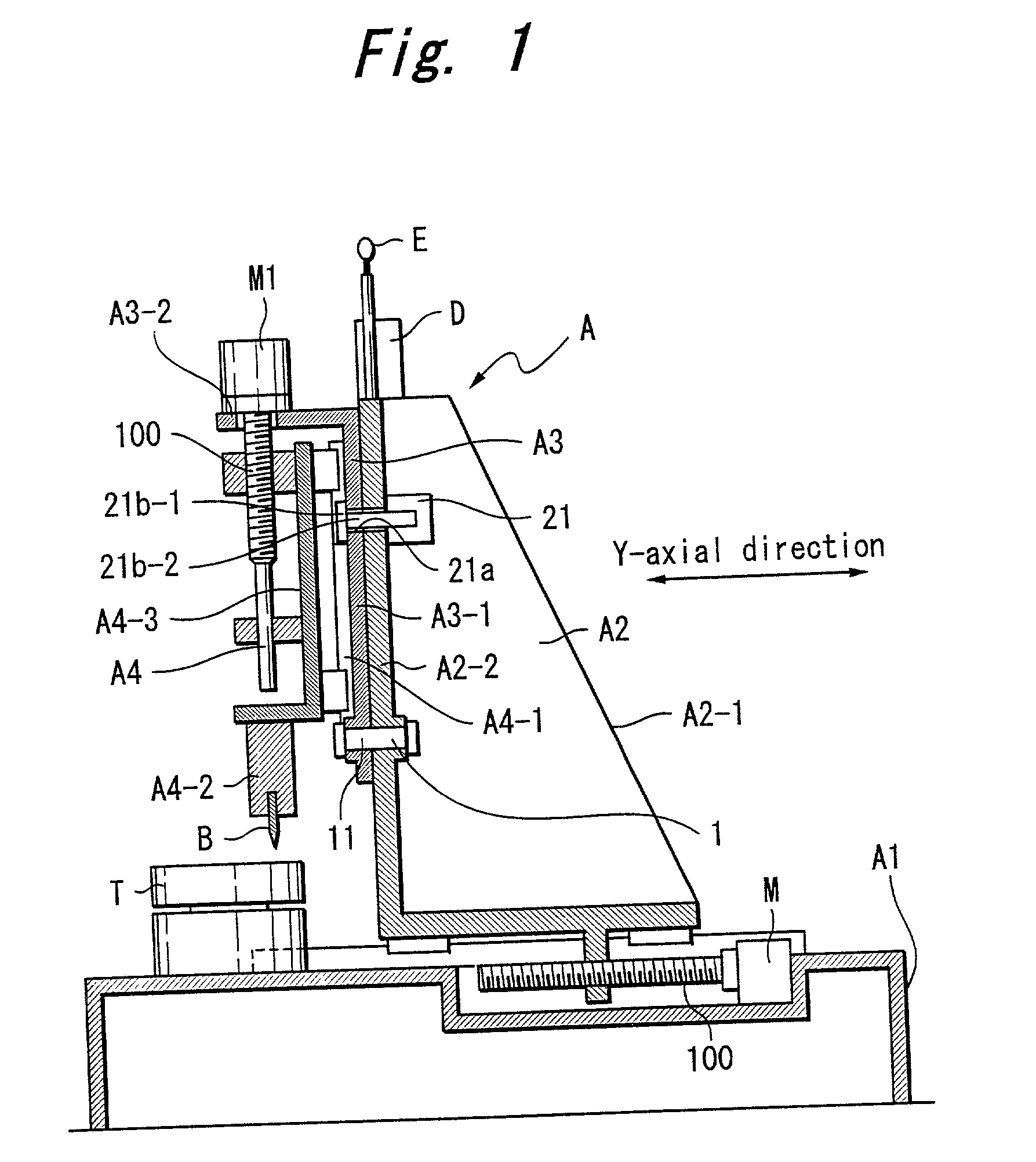
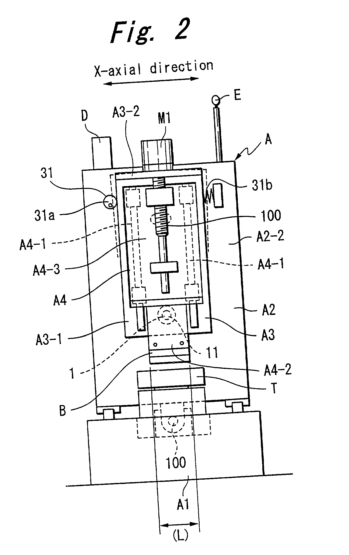
[0073] FIG. 1 and FIG. 2 show a cutting apparatus of a first aspect of the invention provided with a support having a cutting blade on a column, the support being constituted such that a tilting angle in a blade length direction of the cutting blade is capable of controlling, and the cutting blade being vertically movable relative to the support by a driving source provided on the support, FIG. 3-FIG. 5 show a cutting apparatus of the second aspect of the invention constituted such that a cutting blade, a support supporting the cutting blade and a drive source provided on the support are unitized to constitute a plurality of sorts of cutting blade units different in the sort of the drive source, the cutting blade unit is provided on the column replaceably, and a tilting angle in a blade length direction of the cutting blade of respective cutting blade unit is capable of controlling, FIG. 6, FIG. 7, and FIG. 8 show cutting apparat...


PUM

PropertyMeasurementUnit
Angleaaaaaaaaaa
Lengthaaaaaaaaaa
Angleaaaaaaaaaa

Abstract

To provide a cutting apparatus capable of executing cutting or half cutting of a work-piece depending upon quality of the work-piece by producing parallelism between a knife edge of a cutting blade and a mounting face of the work-piece. A support having the blade is provided to a column capable of controlling a tilting angle of the blade in a blade length direction, cutting or half cutting is executed by controlling vertical movement of the blade to the support by a driving source capable of controlling to move linearly provided to the support and by producing a relationship of parallelism to a surface of a table and a knife edge. Respective supports are unitized by being provided with respectively different types driving sources and the blade vertically moved by the driving source and mounted interchangeably and selectively on a column of a cutting apparatus.

Description

[0001] 1. Field of the Invention[0002] The present invention relates to a cutting apparatus suited in cutting or half cutting a work-piece such as a ceramics package, a laminated board of a ceramic green sheet, a film material other than ceramics, a ceramic capacitor, a flexible board, a plastic sheet, and the like.[0003] 1. Description of the Related Art[0004] There are various cutting apparatuses, which are commonly equipped with cutting blades, for example, for cutting or half cutting of a work-piece while moving the cutting apparatus per se or a table mounted with the work-piece, or for cutting or half cutting of the work-piece mounted on an index table while feeding the cutting apparatus per se by a fixed amount.[0005] In case of an index table, the cutting apparatus executes cutting or half cutting of the work-piece while feeding the cutting apparatus per se by a fixed amount at respective time of turning the index table by an angle 90 degrees.[0006] In case of half cutting of...

Claims


Application Information

Patent Timeline
IPC IPC(8): B26D3/08B26D3/12B26D5/08B26D5/12B26D5/16B26D7/01B26D7/20B26D7/22B26D7/26H05K3/00
CPCB26D3/085Y10T29/50B26D5/12B26D5/16B26D7/015B26D7/20B26D7/22B26D7/26B26D7/2628B26D2007/0043B26D2007/0056B26F2001/3886H05K3/0052H05K2203/0228B26D5/08Y10T83/089Y10T83/8847Y10T83/148Y10T83/8867Y10T83/6667B26D3/12
Inventor YASODA, HISASHIWAKABAYASHI, NORIYUKITSUCHIDA, TAKASHI
Owner UHT CORP
Why Eureka
Try Eureka