Free piston engine and self-actuated fuel injector therefor

a self-actuated, piston engine technology, applied in the direction of machines/engines, fuel injection apparatus, charge feed systems, etc., can solve the problems of large thermal losses, drag, and kinetic energy air stream loss, and the need for complex internal combustion or gas turbine engines to supply,

Inactive Publication Date: 2002-07-18
ALEXIUS RICHARD C +1
View PDF0 Cites 24 Cited by
  • Summary
  • Abstract
  • Description
  • Claims
  • Application Information

AI Technical Summary

Problems solved by technology

Propellers and rotors, however, require complex internal combustion or gas turbine engines to supply rotating torque to airfoil shaped blades.
Large amounts of unconstrained, low pressure air is propelled aftward of the propeller / rotor due to the lift and screw action of the airfoil shaped blades, creating thrust and invoking the concomitant slip, drag, and kinetic energy air stream losses.
Large thermal losses are incurred due to the extreme temperatures at which the jet engine must operate.
Free piston engines and compressors disclosed in the literature are complex and heavy devices which go to great lengths to counteract cylinder reaction to the acceleration of the piston(s) by the use of elaborate spring-counterweight mechanisms or tandem pistons synchronized by rack and pinions, linkages, gears, or other mechanical means.
However, there are no feasible, chambered high pressure propulsion systems that utilize unheated atmospheric air, on a continuous basis, as the main propellant medium.
The reason for this is undoubtedly the difficulty of conceiving an engine and compressor combination that is simple and lightweight enough to make it practical.
This is normally accomplished by the use of large, noisy, inefficient fans.

Method used


Image

  • Free piston engine and self-actuated fuel injector therefor
  • Free piston engine and self-actuated fuel injector therefor
  • Free piston engine and self-actuated fuel injector therefor

Examples


second embodiment

Operation of Second Embodiment Engine

[0075] Operation of the engine will be described here, while construction and operation of the preferred fuel injector 18 will be described in following paragraphs.

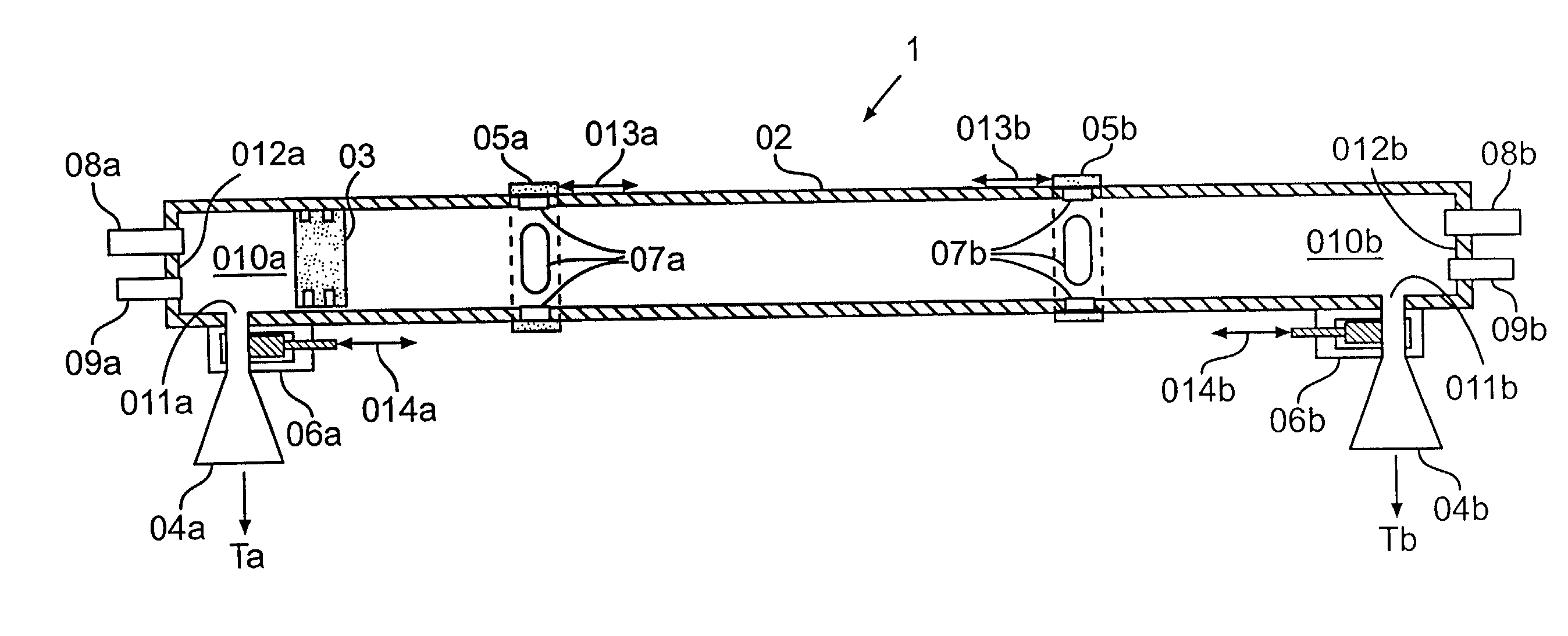
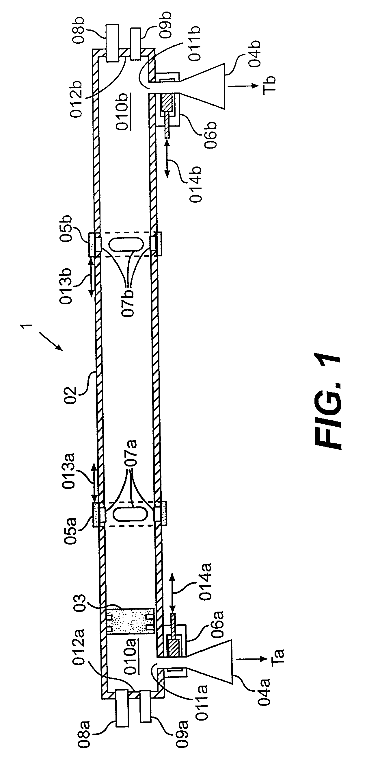
[0076] Assume that piston 3a is in its compression position to the left of cylinder 2a as shown in FIG. 13. When piston 3a is in its compression position, the volume of chamber 5a is at its minimum, and compression pressure therein is at a maximum. Fuel injection has been accomplished and combustion is underway. Piston 3b has opened chamber 5b to exhaust through ports 9b, exhaust duct 10b and exhaust nozzle 11b. Thrust chamber 6a has completed expulsion of its thrust gas and its pressure is approaching atmospheric. Thrust chamber 6b has completed its air intake stroke and is near atmospheric pressure. Injector gas control port 16a is at atmospheric pressure through exhaust port 9a. Check valve 13a is closed since thrust chamber 6b is at low intake pressure.

[0077] As the combined piston...

first embodiment

[0100] Starting of the engine may be accomplished via pneumatic starter valves 26a,26b. Specifically, a source of compressed air may be connected to at least one of the pneumatic starter valves 26a or 26b. For example, compressed air may be passed through pneumatic starter valve 26a and enter combustion chamber 5a thereby moving the piston (3a-4-3b) to the right until the operational state shown in FIG. 17 is achieved. At this point, the fuel injector 18b injects fuel into combustion chamber 5b, combustion begins, and the engine starts. Alternatively, a conventional igniter can be added to at least one of the cylinder heads 21a, 21b and utilized as a starting means with appropriate utilization of the pneumatic starter valves to inject compressed air to move the combined piston 3a-4-3b to a desired position, actuate a fuel injector 18 and thereby start the engine. Furthermore, pneumatic starter valves could also be added to the engine 1 of the first embodiment as an alternative metho...


PUM


Abstract

A simple propulsion engine utilizing unheated atmospheric air as the propellant, and driven by a single cycle (unicycle) engine with internal combustion cylinder and free piston is disclosed. A free piston with an annularly arranged thrust piston to divide a dual-diameter cylinder into two combustion chambers and two thrust chambers is provided. Scavenge feeder lines connected the thrust chambers to the combustion chambers via check valves provide exhaust scavenging, additional thrust output through exhaust nozzles, and feeding of fresh air into the combustion chambers. Also, pressure-actuated fuel injectors utilize pressure changes in respective combustion chambers to inject fuel at the appropriate time. The fuel injector includes an intensifier piston and pintle to raise the fuel pressure.

Description

[0001] This Application is a divisional of co-pending Application No. 09 / 500,468, filed on Feb. 9, 2000, the entire contents of which are hereby incorporated by reference.[0002] 1. Field of the Invention[0003] This invention is in the field of propulsive machines cooperating with internal combustion, free piston engines and compressors to produce motive power, lifting, or other uses. This invention also relates to a self-actuated fuel injector that may be utilized in such an engine.[0004] 2. Background of the Invention[0005] Numerous inventions known in the prior art have been developed, and many proposed which are based on the Newtonian principle of reactive propulsion. Propellers and helicopter rotors, jet engines, and rockets are the principal examples of that genre.[0006] Propellers and rotors, however, require complex internal combustion or gas turbine engines to supply rotating torque to airfoil shaped blades. Large amounts of unconstrained, low pressure air is propelled aftwa...

Claims


Application Information

Patent Timeline
Patent Type & Authority Applications(United States)
IPC IPC(8): F02B71/04F02M49/02
CPCF02B71/04F02M49/02
Inventor ALEXIUS, RICHARD C.ALEXIUS, KARL R.ALEXIUS, RENEE S.
Owner ALEXIUS RICHARD C
Why Eureka
Try Eureka