Opposed piston opposed cylinder free piston engine

a free piston engine and opposed piston technology, applied in the direction of positive displacement liquid engine, piston pump, machine/engine, etc., can solve the problems of large friction, limited efficiency, and limited power density, and achieve the effect of reducing time, reducing friction, and efficient producing hydraulic power

Inactive Publication Date: 2005-10-11
FORD GLOBAL TECH LLC
View PDF13 Cites 19 Cited by
  • Summary
  • Abstract
  • Description
  • Claims
  • Application Information

AI Technical Summary

Benefits of technology

[0014]An additional advantage of the present invention is that an OPOC engine efficiently produces hydraulic power because of its ability to change direction fast, minimizing the time at zero speed and output. Moreover, it generates the hydraulic energy at half the operating speed of the total piston stroke per cycle, because each pumping chamber is only tied to one of the combustion chamber piston assemblies, thus operating through only one half of the total engine stroke. This ability to pump at one half the engine stroke can be critical when the engine power density is limited by the maximum allowable pumping velocity.
is that an OPOC engine efficiently produces hydraulic power because of its ability to change direction fast, minimizing the time at zero speed and output. Moreover, it generates the hydraulic energy at half the operating speed of the total piston stroke per cycle, because each pumping chamber is only tied to one of the combustion chamber piston assemblies, thus operating through only one half of the total engine stroke. This ability to pump at one half the engine stroke can be critical when the engine power density is limited by the maximum allowable pumping velocity.

Problems solved by technology

While these conventional types of engines have seen great improvements in efficiency in recent years, due to the nature of the engines, that efficiency is still limited.
In particular, the power density is limited because the mechanically fixed motion of the pistons fixes the compression ratio.
Moreover, all of the moving parts that direct the movement of the pistons (and camshafts and engine valves as well) create a great deal of friction, which takes energy from the engine itself to overcome.
The resulting lower power density means that the engine will be larger and heavier than is desired.
Also, the flexibility in the engine design and packaging is limited because of all of the mechanical connections that must be made.
However, these types of engines have not come into common use because, with free pistons, the complexity of engine operation is greatly increased.
However, linear generators are not particularly efficient at producing power—especially when compared to conventional rotary generators.

Method used


Image

  • Opposed piston opposed cylinder free piston engine
  • Opposed piston opposed cylinder free piston engine
  • Opposed piston opposed cylinder free piston engine

Examples


Embodiment Construction

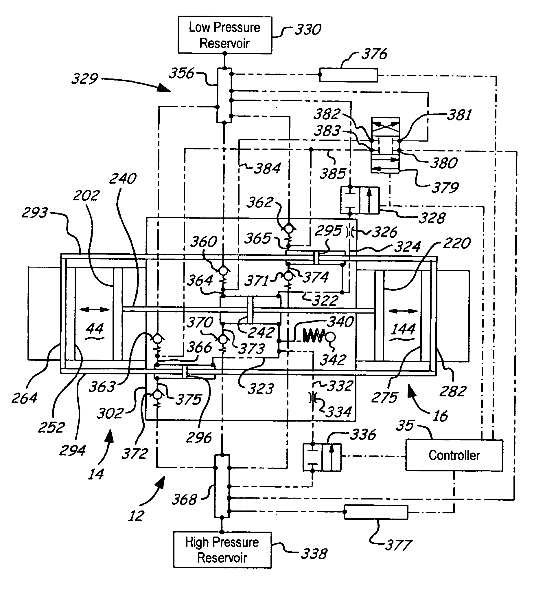
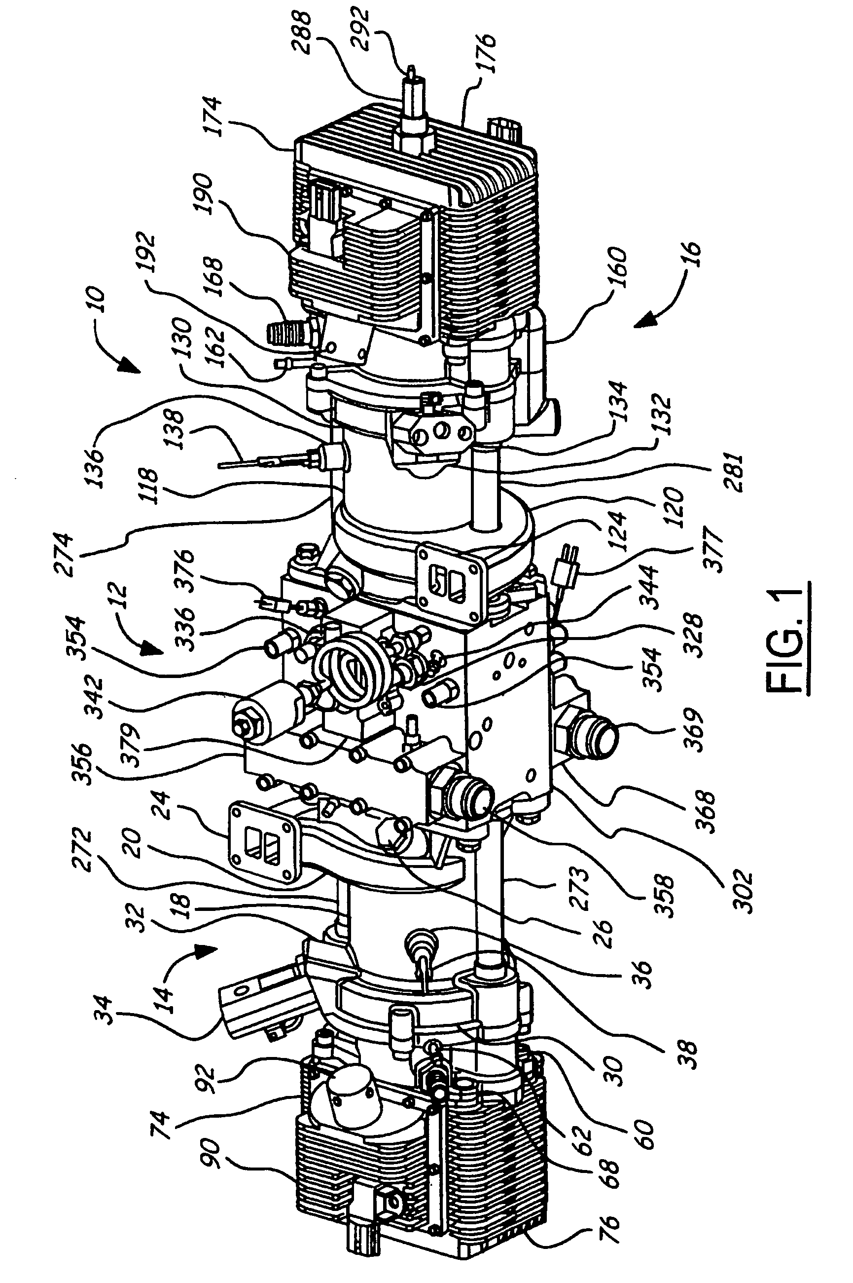
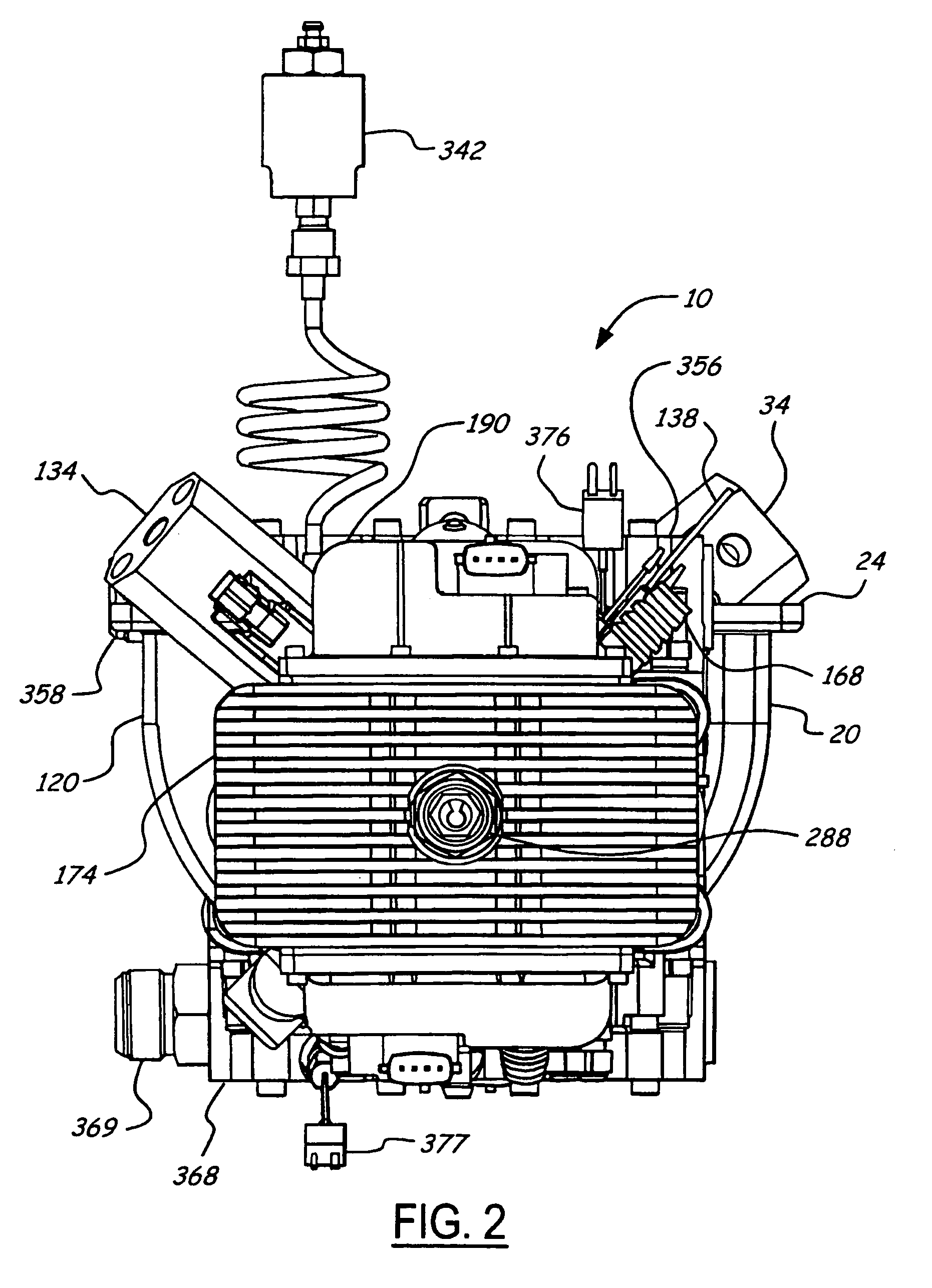
[0030]FIGS. 1–11 illustrate an opposed piston, opposed cylinder, hydraulic, free piston engine 10. The engine 10 includes a hydraulic pump block assembly 12, with a first piston / cylinder assembly 14 extending therefrom, and a second piston / cylinder assembly 16 extending from the hydraulic pump block assembly 12 in the opposite direction so they are in line. The timing of the first piston / cylinder assembly 14 is opposite to the timing of the second piston / cylinder assembly 16. Thus, when one is at top dead center, the other is at bottom dead center. Moreover, the motion is along or parallel to a single axis of motion. This configuration of free piston engine allows for a more inherently balanced engine.

[0031]Additionally, the following description discloses an engine that not only stores energy produced by the engine in the form of pressurized fluid, but also employs some of this pressurized fluid to start and, at times, assist in controlling the engine operation and maintaining the ...


PUM


Abstract

A free piston engine is configured with a pair of opposed engine cylinders located on opposite sides of a fluid pumping assembly. An inner piston assembly includes a pair of inner pistons, one each operatively located in a respective one of the engine cylinders, with a push rod connected between the inner pistons. The push rod extends through an inner pumping chamber in the fluid pumping assembly and forms a fluid plunger within this chamber. An outer piston assembly includes a pair of pistons, one each operatively located in a respective one of the engine cylinders, with at least one pull rod connected between the outer pistons. The pull rod extends through an outer pumping chamber in the fluid pumping assembly and forms a fluid plunger within this chamber.

Description

BACKGROUND OF INVENTION[0001]The present invention relates to free piston engines, and more particularly to free piston engines having an opposed piston opposed cylinder configuration.[0002]Conventionally, internal combustion engines have operated with the motion of the pistons mechanically fixed. For example, a conventional internal combustion engine for a motor vehicle includes a crankshaft and connecting rod assemblies that mechanically determine the motion of each piston within its respective cylinder. This type of engine is desirable because the position of each piston is know for any given point in the engine cycle, which simplifies timing and operation of the engine. While these conventional types of engines have seen great improvements in efficiency in recent years, due to the nature of the engines, that efficiency is still limited. In particular, the power density is limited because the mechanically fixed motion of the pistons fixes the compression ratio. Moreover, all of t...

Claims


Application Information

Patent Timeline
Patent Type & Authority Patents(United States)
IPC IPC(8): F02B71/00B60K1/00B60K16/00F02B71/04F02B75/28F04B17/00F04B19/00F04B35/00
CPCF02B71/04F04B19/003F01B11/006F02B75/28Y02T10/90
Inventor HOFBAUER, PETER
Owner FORD GLOBAL TECH LLC
Why Eureka
Try Eureka