Supercharged two-cycle engines employing novel single element reciprocating shuttle inlet valve mechanisms and with a variable compression ratio

a two-cycle engine and reciprocating shuttle technology, applied in the direction of machines/engines, oscillatory slide valves, mechanical equipment, etc., can solve the problems of affecting reducing the efficiency of combustion, so as to achieve high efficiency at all engine speeds, the effect of reducing the number of problems

Inactive Publication Date: 2008-03-11
WIESEN BERNARD
View PDF4 Cites 19 Cited by
  • Summary
  • Abstract
  • Description
  • Claims
  • Application Information

AI Technical Summary

Problems solved by technology

The more out-of-phase the opposed-pistons are arranged, to increase the time allowed for scavenging and supercharging, the further apart the piston crowns are when the leading piston reaches top dead center and the more detrimental this arrangement is in regard to combustion efficiency.
This out-of-phase piston arrangement also complicates the problem of obtaining a balance of the opposing inertial forces of the pistons, whereby the potential advantages of opposed-piston two-cycle engines are lost.
An often unrecognized consequence resulting from this out-of-phase piston arrangement is that there is a substantial disparity in the amount of power transmitted to the shaft from the leading piston, which is essentially much greater than that transmitted from the following piston, by as much as 20% or even more.
This disparity increases with the phase angle and constitutes an inherent flaw in engines of this category.
It remains a question as to whether the increased specific output outweighs the disadvantages of the required out-of-phase mechanical arrangements and the type's inability to keep pace with the current demands for improved in-cylinder combustion technology.
Previous stepped-pistons were used as a scavenging mechanism for two-cycle engines but without a uniflow scavenging valve mechanism are unable to supercharge an engine cylinder.
Eliminating the need for the addition of a complex valve mechanism operated from the engine crankshaft or camshaft that requires the use of cams, shafts, connecting rods, levers, springs and other elements, some of which can be very expensive, requiring both precise manufacture and skilled assembly, with frequent maintenance and adjustment and many known problems involving lubrication and wear.
Until now no existing type of inlet valve could produce the essential requirements of presenting the maximum throughway inlet area to the air in the minimum time.
Eliminating the need for any complex valve mechanism operated from the engine crankshaft or camshaft that requires the use of cams, connecting rods, levers, springs and other elements, some of which are very expensive, requiring precise manufacture and skilled assembly with frequent maintenance and adjustment with many known problems involving lubrication and wear.
The lack of a squish area between the opposing piston crowns is highly disadvantageous due to the less favorable ignition conditions that thereby create increased noxious emissions.
Altering the phase relationship between the opposed-pistons impairs the naturally very high level of dynamic balance within each cylinder that occurs when the opposed-pistons are in phase.

Method used


Image

  • Supercharged two-cycle engines employing novel single element reciprocating shuttle inlet valve mechanisms and with a variable compression ratio
  • Supercharged two-cycle engines employing novel single element reciprocating shuttle inlet valve mechanisms and with a variable compression ratio
  • Supercharged two-cycle engines employing novel single element reciprocating shuttle inlet valve mechanisms and with a variable compression ratio

Examples


Embodiment Construction

[0068]Some conventional details of engine construction may not be described.

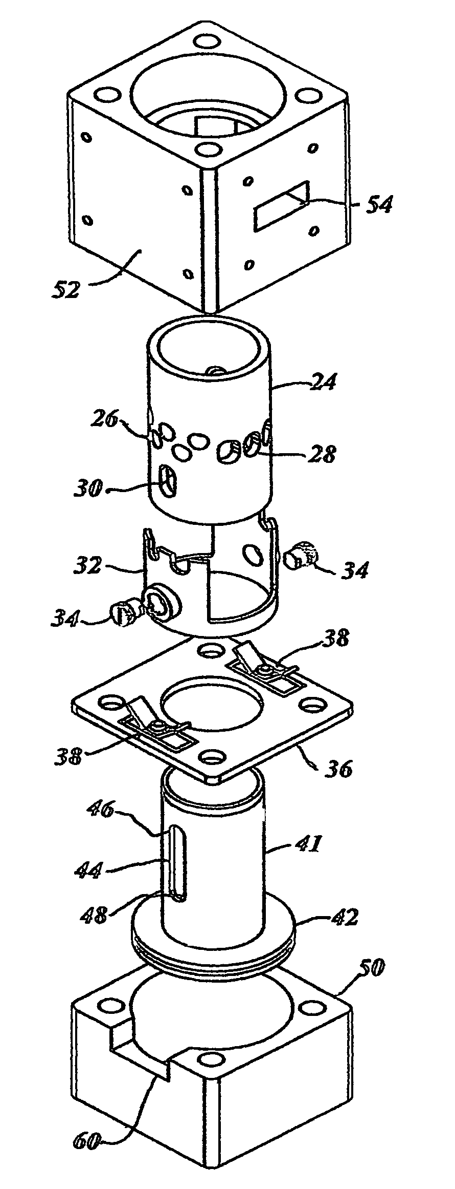
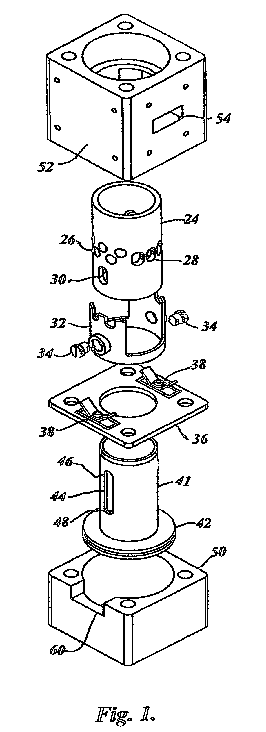
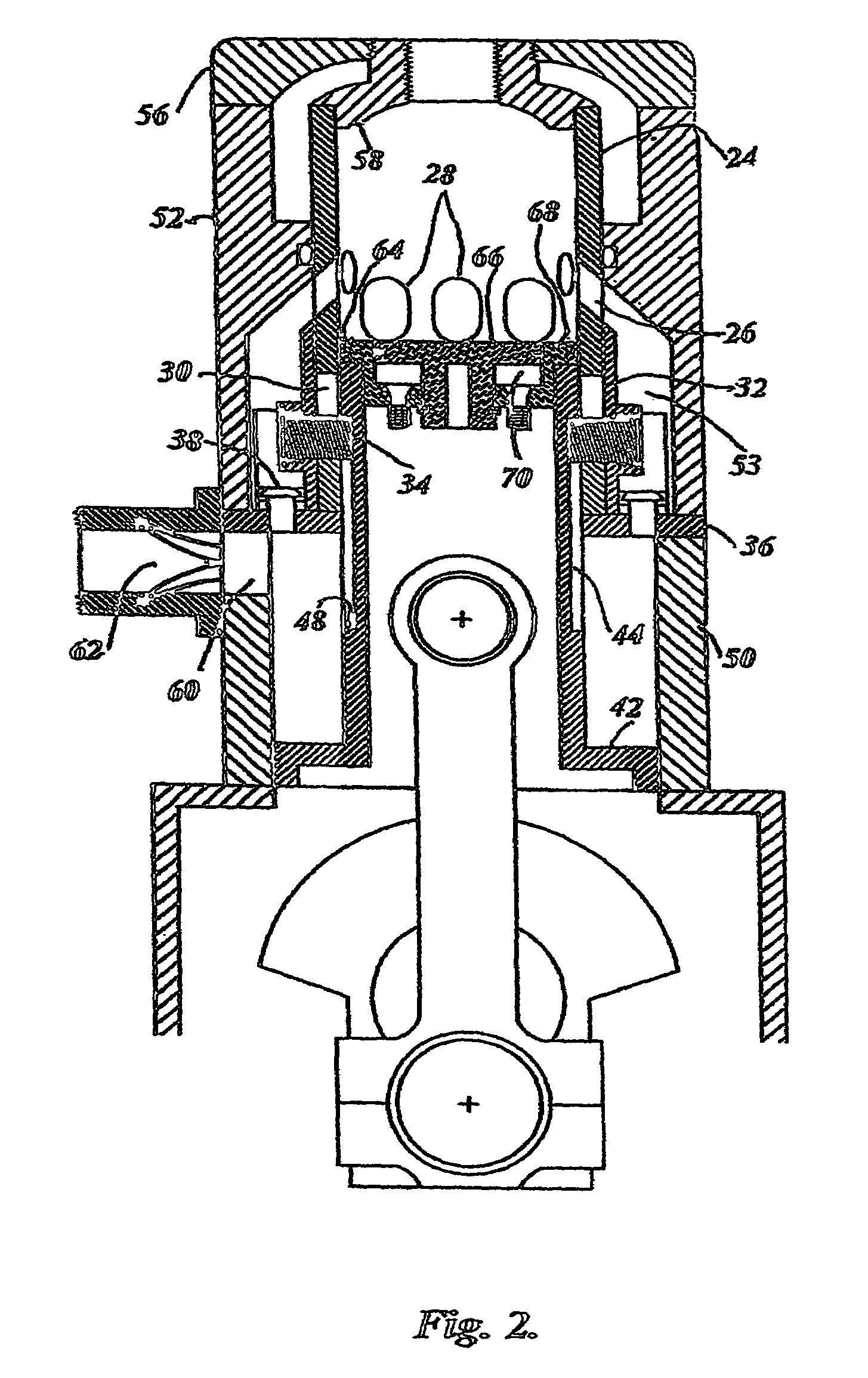
[0069]The sequence of operation is best described beginning with the piston at bottom dead center. As the power piston 41 begins it's upward stroke, the combined rising compressor piston 42 forces air past one-way transfer valves 38 in the valve plate 36 that separates the compressor cylinder 50 from the plenum 53. The air flows from the compressor cylinder 50 through the transfer valves 38 in the valve plate 36 into and through the plenum 53 and on through the open inlet ports 26, into the power cylinder 24, thereby filling the power cylinder 24 with a fresh air charge, assuring instant starting or further cleansing and cooling the power cylinder 24 of the previous combustion event. As the power piston 41 continues to rise, it covers the exhaust ports 28 preventing any further loss of air from the power cylinder 24. The charge of compressed air that continues to enter the power cylinder 24 from the plenum 5...


PUM


Abstract

This invention relates to novel reciprocating shuttle inlet valves, effective with every type of two-cycle engine, from small high-speed single cylinder model engines, to large low-speed multiple cylinder engines, employing spark or compression ignition. Also permitting the elimination of out-of-phase piston arrangements to control scavenging and supercharging of opposed-piston engines. The reciprocating shuttle inlet valve (32) and its operating mechanism (34) is constructed as a single and simple uncomplicated member, in combination with the lost-motion abutments, (46) and (48), formed in a piston skirt, obviating the need for any complex mechanisms or auxiliary drives, unaffected by heat, friction, wear or inertial forces. The reciprocating shuttle inlet valve retains the simplicity and advantages of two-cycle engines, while permitting an increase in volumetric efficiency and performance, thereby increasing the range of usefulness of two-cycle engines into many areas that are now dominated by the four-cycle engine.

Description

CROSS-REFERENCE TO RELATED APPLICATIONS[0001]This application claims the priority benefit of U.S. Provisional Patent Application Ser. No. 60 / 700,231 filed on Jul. 14, 2005.STATEMENT OF GOVERNMENT INTEREST[0002]This invention was made in part with United States Government support under Contract No. NAS3-01035 awarded by the National Aeronautics and Space Administration (NASA). The United States Government has certain rights in the claims of this invention and any resulting patent.BACKGROUND OF THE INVENTION[0003]The present invention relates to supercharged two-cycle engines and more particularly to novel reciprocating shuttle inlet valves highly suited for employment with all engines in this category, designed to permit the effective supercharging and scavenging of an engine cylinder. The entire reciprocating shuttle inlet valve and its operating mechanism is constructed as a single and simple uncomplicated member, operated by an ingenuous lost-motion arrangement between the recipro...

Claims


Application Information

Patent Timeline
Patent Type & Authority Patents(United States)
IPC IPC(8): F01L3/20
CPCF01L1/38F01L7/04F02B2075/025
Inventor WIESEN, BERNARD
Owner WIESEN BERNARD
Why Eureka
Try Eureka