Image forming apparatus

a technology of forming apparatus and forming chamber, which is applied in the direction of electrographic process apparatus, instruments, corona discharge, etc., can solve the problems of consuming a large amount of toner, having to supply a large amount of developer, and unable to achieve the space for mounting potential sensors, etc., to achieve stable reproduction of high-quality images

Inactive Publication Date: 2002-09-12
HITACHI PRINTING SOLUTIONS LTD
View PDF0 Cites 6 Cited by
  • Summary
  • Abstract
  • Description
  • Claims
  • Application Information

AI Technical Summary

Benefits of technology

[0009] Accordingly, an object of the present invention is to provide an image forming apparatus, which restricts disturbance of a potential patch in the case where a potential sensor for detecting the potential patch is provided downstream side of a developing device of a multiple developing roller type to enable stable reproduction of a high quality image for a long period.
[0013] According to the third aspect of the present invention, an image forming apparatus comprises: an image carrier; charging means for charging an image carrier; exposure means for exposing image on the charged image carrier for forming a exposure portion potential; developing means including a plurality of developing rollers arranged in opposition with a surface of the image carrier, biasing applying means for applying a developing bias to the plurality of developing roller and a two component developer, for supplying a developer on the image carrier and forming a developed image on the image carrier; transfer means for transferring the developed image formed on the image carrier onto a printing medium; a potential sensor provided downstream side of moving direction of the image carrier relative to the developing means for detecting a charge potential and an exposure potential on the image carrier; and control means for applying the developing bias at a value restricting splashing of carrier to the surface of the image carrier when the charge potential region passes through the developing means, and avoiding the developing bias to a value for restricting deposition of toner to the exposure portion potential when the exposure portion potential region passes across the developing means.
[0015] charging means for charging an image carrier; exposure means for exposing image on the charged image carrier for forming a exposure portion potential; developing means including a plurality of developing rollers arranged in opposition with a surface of the image carrier, biasing applying means for applying a developing bias to the plurality of developing roller and a two component developer, for supplying a developer on the image carrier and forming a developed image on the image carrier; transfer means for forming a transfer nip portion by contacting with the surface of the image carrier and transferring the developed image formed on the image carrier onto a printing medium in the transfer nip; a potential sensor provided downstream side of moving direction of the image carrier relative to the developing means for detecting a charge potential and an exposure potential on the image carrier; and control means for applying the developing bias at a value restricting splashing of carrier to the surface of the image carrier when the charge potential region passes through the developing means, and avoiding the developing bias to a value for restricting deposition of toner to the exposure portion potential when the exposure portion potential region passes across the developing means.

Problems solved by technology

In case of the toner patch system, since the toner image has to be formed on the image carrier body, extra amount of toner is consumed.
However, upon speeding up a printing speed of the image forming apparatus, greater amount of developer has to be supplied to the image carrier body.
However, when the multiple stage developing roller type developing device us employed, associating with increasing of size, difficulty is encountered for certainly attaining space for mounting the potential sensor between the exposure device and the developing device.
On the other hand, mounting the potential sensor between the exposure device and the developing device is not always appropriate in view point of speeding of the printing speed.
Namely, it is possible that the potential patch may pass below the potential sensor before the potential of the exposure portion drops down to the predetermined potential due to optical response characteristics of the image carrier body (photo conductor) to make it impossible to accurately detect the potential patch.

Method used


Image

  • Image forming apparatus
  • Image forming apparatus
  • Image forming apparatus

Examples


Embodiment Construction

[0052] The present invention will be discussed hereinafter in detail in terms of the preferred embodiment of the present invention with reference to the accompanying drawings. In the following description, numerous specific details are set forth in order to provide a thorough understanding of the present invention. It will be obvious, however, to those skilled in the art that the present invention may be practiced without these specific details. In other instance, well-known structure is not shown in detail in order to avoid unnecessary obscurity of the present invention.

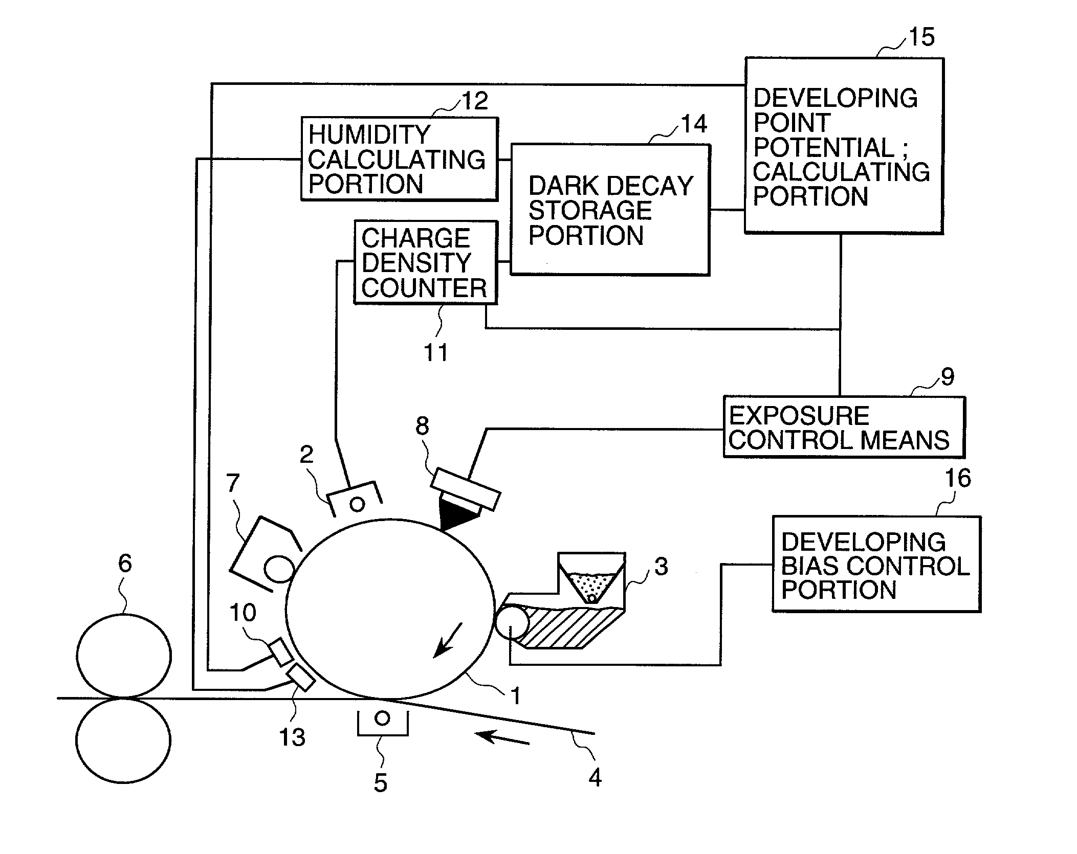
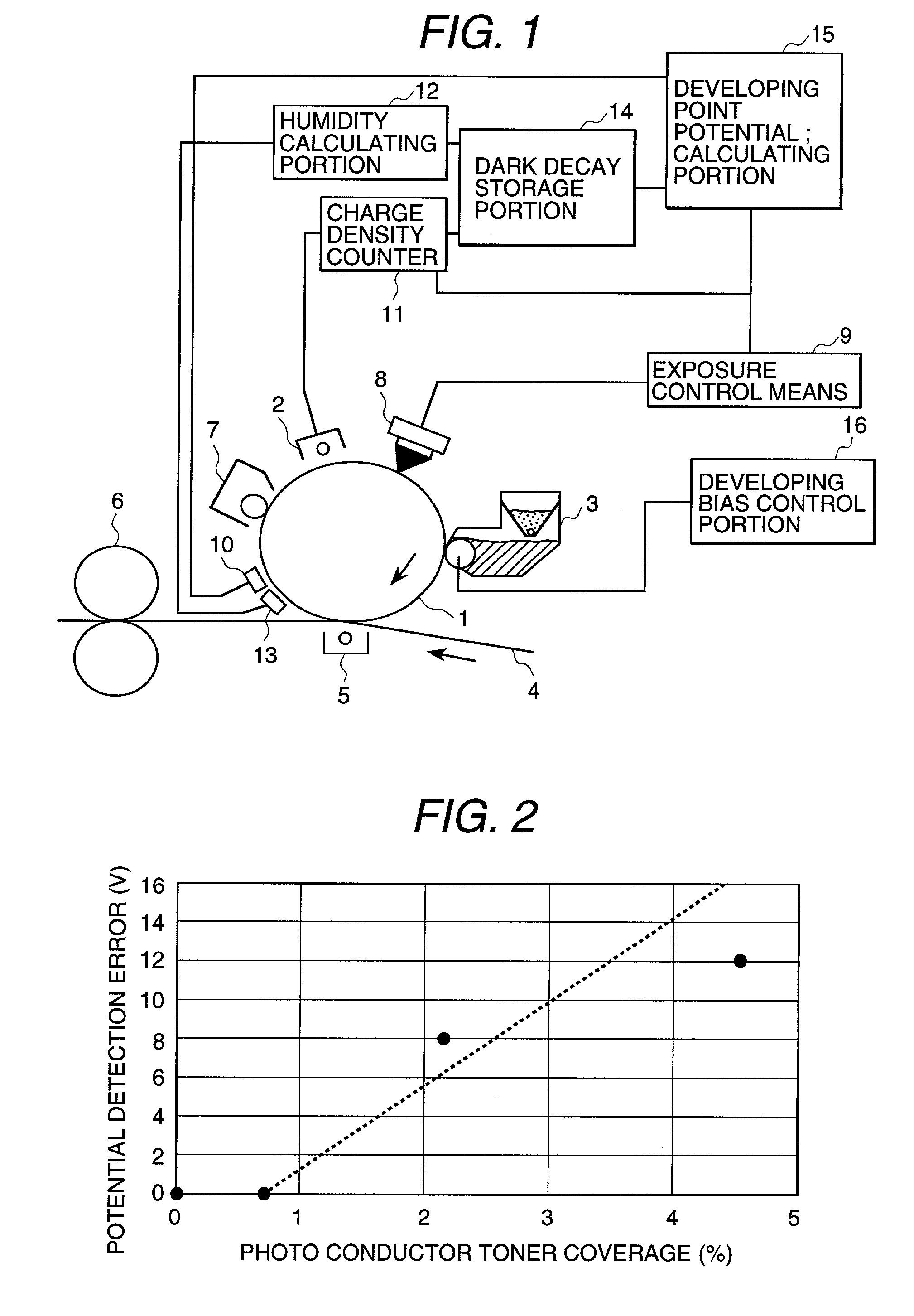
[0053] FIG. 1 is a diagrammatic block diagram of the preferred embodiment of an image forming apparatus according to the present invention. In the drawings, the reference numeral 1 denotes a photo conductor drum 1 as one example of an image carrier, 2 denotes a charger, 3 denotes a developing device, 4 denotes a printing paper as one example of a printing medium, 5 denotes a transfer device, 6 denotes a fixing devic...


PUM


Abstract

An image forming apparatus restricts disturbance of a potential patch in the case where a potential sensor for detecting the potential patch is provided downstream side of a developing device of a multiple developing roller type to enable stable reproduction of a high quality image for a long period. The apparatus includes a potential sensor provided downstream side of moving direction of the image carrier relative to the developing means for detecting a potential on the image carrier, and controller setting the developing bias to a value restricting disturbance of a potential portion as an object for potential detection by the potential sensor by the developer when the potential portion passes across the developing means.

Description

BACKGROUND OF THE INVENTION[0001] The present invention relates to an image forming apparatus represented by a printer, a copy machine, a facsimile and so on.[0002] In an image forming apparatus represented by a printer, a copy machine, a facsimile and so on, it has been well known so-called an electrophotographic process, in which a photo conductor as an image carrier is charged, an image exposure on the charged photo conductor is performed for recording an electrostatic latent image, a developer is supplied to the photo conductor carrying the electrostatic latent image for developing the electrostatic latent image, and a toner image thus formed on the photo conductor is transferred to a paper, an OHP sheet or a recording body, such as an intermediate transfer body, to obtain a printed image.[0003] In the image forming apparatus of this kind, in consideration for stably reproducing a high image quality for a long period, there has been known a mechanism, in which a patch is formed ...

Claims


Application Information

Patent Timeline
Patent Type & Authority Applications(United States)
IPC IPC(8): G03G15/00G03G15/06
CPCG03G15/065G03G15/5037G03G2215/00054
Inventor KUBOTA, KEISUKEMITSUYA, TERUAKIMABUCHI, HIROYUKIISHII, MASAYOSHIAKATSU, SHINICHI
Owner HITACHI PRINTING SOLUTIONS LTD
Why Eureka
Try Eureka