Method of controlling an optical disk apparatus

a technology of optical disk and control device, which is applied in the direction of digital signal error detection/correction, instruments, recording signal processing, etc., can solve the problems of reducing the yield of products, affecting the accuracy of optical disk, and increasing the influence of aberration, so as to simplify the operation of adjustment and control, and simplify the calculation process. , the effect of stable reproduction and/or recording

Inactive Publication Date: 2007-01-16
RICOH KK
View PDF17 Cites 10 Cited by
  • Summary
  • Abstract
  • Description
  • Claims
  • Application Information

AI Technical Summary

Benefits of technology

[0062]The present invention also provides a method of controlling an optical disk apparatus, including the steps of rotating an optical disk which is flexible, irradiating light from an optical pickup to a recording surface of the optical disk on which writing / reading of information is performed, stabilizing vibration of the optical disk occurring in a rotary axial direction with a stabilizing unit by pressure difference of air flow at least on a portion where writing / reading is performed, detecting a focus error signal with a focus error detection unit for use in servo control of a focus position of the optical pickup, analyzing a residual focus error signal that is detected by the focus error detection unit to indicate the focus error remaining despite the servo control, and adjusting a positional relation between the optical disk and the stabilizing unit in a three dimensional space according to a value obtained by analyzing the residual focus error signal. Thus structured, the state of surface vibration observed from the side of the optical pickup (i.e. the state of actual surface vibration which prevents steady recording / reproduction operation) can be precisely determined according to a waveform of the residual focus error signal, and the portion of the optical disk in which surface vibration is stabilized and the focus position of the optical disk which is focused by the optical pickup can be precisely matched by adjusting the positional relation between the optical disk and the stabilizing member, to thereby allow stable reproduction and / or recording at the position where there is little surface vibration. Furthermore, such optical disk apparatus can correspond easily to high NA optical pickup having narrow defocus margin and narrow work distance since the value of surface vibration occurring at a position of the optical disk at which recording / reproducing is performed can be reduced to a considerably small value.
[0063]The present invention also provides a method of controlling an optical disk apparatus, including the steps of a) rotating an optical disk which is flexible, b) irradiating light from an optical pickup to a recording surface of the optical disk on which writing / reading of information is performed, c) stabilizing vibration of the optical disk occurring in a rotary axial direction with a stabilizing unit by pressure difference of air flow at least on a portion where writing / reading is performed, d) detecting a focus error signal with a focus error detection unit for use in servo control of a focus position of the optical pickup, e) analyzing a residual focus error signal that is detected by the focus error detection unit to indicate the focus error remaining despite the servo control, f) adjusting a positional relation between the optical disk and the stabilizing unit in a three dimensional space according to a value obtained by analyzing the residual focus error signal, g) predetermining a standard condition for three-dimensionally adjusting a positional relation between the optical disk and the stabilizing member by applying the steps a) to f) to various optical disks having different specifications, and h) applying the steps a) to f) according to a given optical disk according to a corresponding one of the predetermined standard conditions. With such method, by predetermining the representative conditions for control with respect to the optical disk targeted for use, the position where the optical pickup focuses upon the optical disk and the position where surface vibration of the optical disk is stabilized can be precisely matched according to the said conditions for control. This method simplifies operation for adjustment and control, and also simplifies the process for calculation, to thereby provide a more simple and inexpensive optical disk apparatus.
[0064]In the aforementioned method of controlling an optical disk apparatus the step h) includes a step of performing the steps a) to f) and a step of performing the steps a) to f) according to the standard condition as fine adjustment. With such method, the operation for adjustment and control can be more simple and faster.

Problems solved by technology

However, enlarging NA of the objective lens and shortening the wavelength of light may result to an increase in influence of aberration in a case where applied light is weakened.
Furthermore, since the distance between the objective lens and recording surface of an optical disk becomes shorter by using the objective lens of high NA, the objective lens and optical disk may collide before the focus servo becomes fully effective during the start-up period, unless surface vibration or axial runout on the disk is sufficiently controlled.
Such requirements may reduce the yield of products, which may then result to cost rise of optical disks.
As a result, the optical disk vibrates to thereby cause surface vibration at high frequency.
The surface vibration at high frequency often falls in a frequency range for which mechanical focus servo control cannot handle, and therefore, residual servo error cannot be sufficiently eliminated.
Furthermore, surface vibration due to mutual sliding of the optical disk and objective lens causes creation of dirt / dust, and leads to various errors.
Particularly, in Japanese laid-open patent publication No. 7-105657 where the record film is positioned on the side facing the stabilization plate, the mutual sliding also causes damage upon the optical disk, and directly results to error in recording / reproducing.
Nevertheless, employing a gap sensor such as the electrostatic capacity type displacement sensor is too costly and is unrealistic to be applied to a typical, widely used optical disk drive.

Method used


Image

  • Method of controlling an optical disk apparatus
  • Method of controlling an optical disk apparatus
  • Method of controlling an optical disk apparatus

Examples


first embodiment

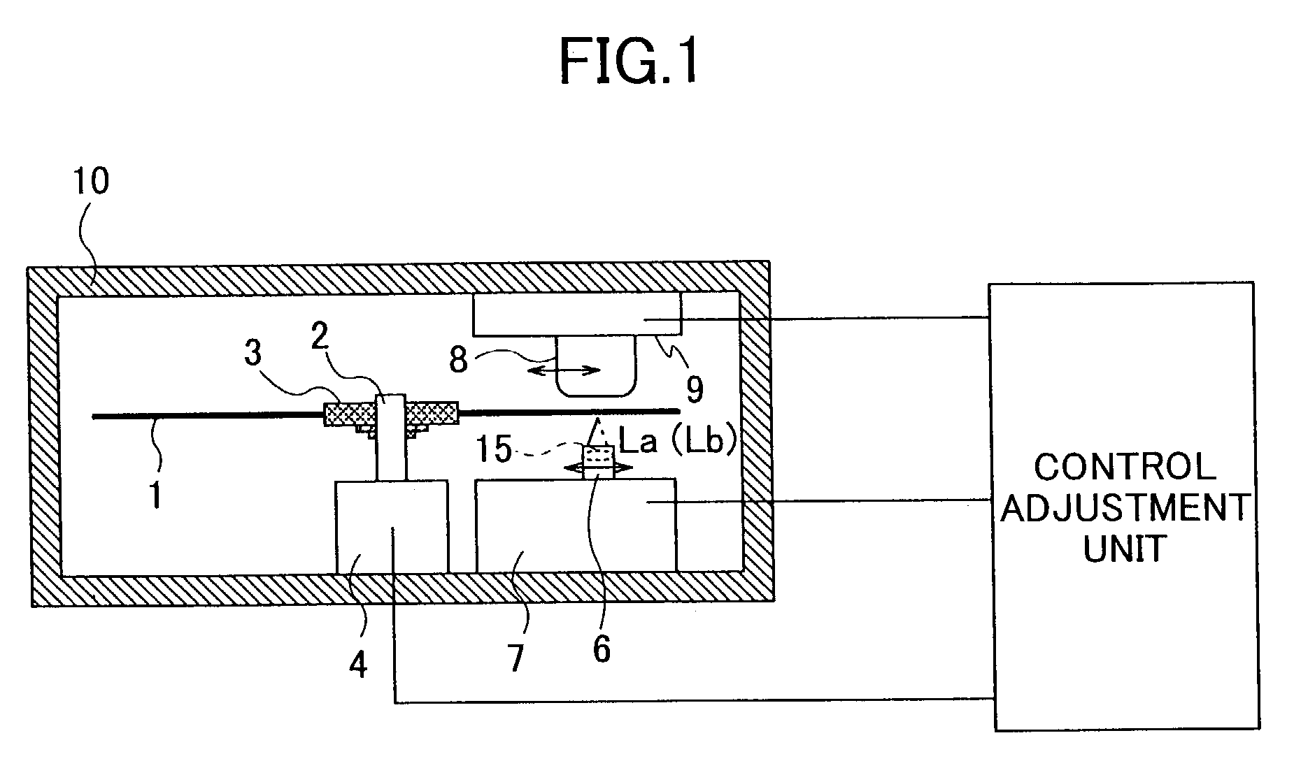
[0091]FIG. 1 shows an optical disk apparatus for the present invention, in which numeral 1 denotes an optical disk having a flexible sheet-like form, numeral 2 denotes a spindle shaft holding a hub 3 of the optical disk 1, numeral 4 denotes a spindle motor performing rotation drive of the spindle shaft 2, numeral 6 denotes an optical pickup writing / reading information onto / from the optical disk 1, numeral 7 denotes a pickup positioning mechanism moving the optical pickup 6 along a radius direction of the optical disk 1, numeral 8 denotes a stabilizing member serving to prevent surface vibration of the optical disk 1 and being positioned on the opposite side from the optical pickup 6 having the optical disk 1 disposed therebetween, and numeral 9 denotes a stabilizing member positioning mechanism serving to move the stabilizing member 8 in a radius direction of the optical disk 1 in association with movement of the optical pickup 6. These respective members / components are housed in an...

second embodiment

[0133]FIG. 10 is a schematic view showing an optical disk apparatus according to the present invention, in which 50 denotes a z-axis stabilizing member position control portion, 51 denotes a z-axis pickup position control portion, 52 denotes an x-axis spindle tilt angle control portion, 54 denotes an x-axis spindle position control portion, 55 denotes a y-axis stabilizing member tilt angle control portion, and 56 denotes a y-axis pickup tilt angle control portion. The tilt angle for the y-axis stabilizing member tilt angle control portion 55 can be adjusted in a case where the surface center position O of the stabilizing member. 8 serve as the rotary center. The tilt angle for the y-axis pickup tilt angle control portion 56 can be adjusted in a case where the focal point position of the optical pickup 6 serve as the rotary center. The y-axis stabilizing member tilt angle control portion 55 and the y-axis pickup tilt angle control portion 56 always move in association with each other...

third embodiment

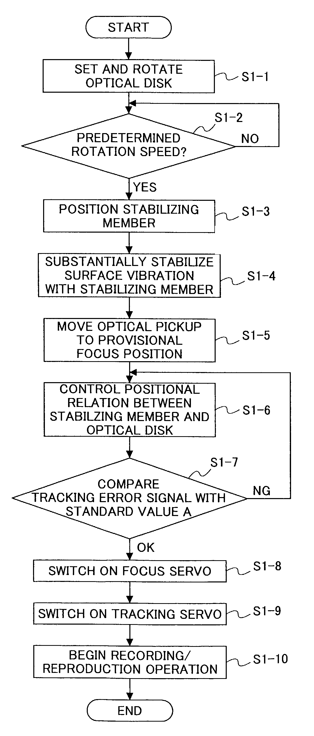
[0143]Adjustment and control for stabilizing surface vibration for the third embodiment will be explained with reference-the flow chart shown in FIG. 12.

[0144]When a start signal is inputted into a CPU (central processing unit), the spindle motor 4 starts and rotates the optical disk 1 (step S3-1). When the optical disk 1 reaches a predetermined rotation speed (YES in step S3-2), the stabilizing member 8 is moved in a radial direction of the optical disk 1, the estimated value B is read out, and the stabilizing member 8 is set three dimensionally with respect to the optical disk 1 (step S3-3). The stabilizing member / pickup space adjusting portion 45 performs adjustment so that a provisional focus position of the optical pickup 6 would match with the surface center position O of the stabilizing member 8 (step S3-4).

[0145]Then, the CPU monitors and analyzes the tracking error signal detected from a detector of the optical pickup 6 in a state where the focus servo is switched off, to t...


PUM

PropertyMeasurementUnit
wavelengthaaaaaaaaaa
widthaaaaaaaaaa

Abstract

An optical disk apparatus includes a rotary driving unit rotating an optical disk which is flexible, an optical pickup irradiating light upon a recording surface of the optical disk on which writing/reading of information is performed, a stabilizing unit stabilizing vibration of the optical disk in a rotary axial direction by using pressure difference of air flow at least on a portion where writing/reading is performed, and being disposed on a side of the optical disk opposite to a side on which the recording surface is provided, and a control-adjustment unit analyzing a value of a tracking error signal of the optical disk obtained by scanning along a groove of the optical disk with use of the optical pickup, comparing the analyzed value of the tracking error signal of the optical disk and a value priorly obtained by scanning along a groove of a standard disk prepared beforehand, and adjusting a positional relation between the optical disk and the stabilizing member in a three dimensional space according to the result of the comparison.

Description

BACKGROUND OF THE INVENTION[0001]1. Field of the Invention[0002]The present invention generally relates to an optical disk apparatus using a flexible sheet-like optical disk as an optic information recording medium and having a stabilizing unit therein which stabilizes surface vibration in a rotary axial direction of the optical disk by using pressure difference of air flow at a portion of the optical disk at which writing / reading is performed, and a method of controlling the optical disk apparatus, and particularly relates to a technique for adjusting a positional relation between the optical disk and the stabilizing member.[0003]2. Description of the Related Art[0004]Optical disks are demanded to store mass digitized data in response to, for example, the recent digitization of television broadcasting. A basic method of improving recording density on the optical disks is to reduce the diameter of a beam spot used for recording / reproducing information onto / from the optical disk.[000...

Claims


Application Information

Patent Timeline
Patent Type & Authority Patents(United States)
IPC IPC(8): G11B7/095G11B7/09
CPCG11B19/2009G11B7/0956G11B7/0946G11B7/0901G11B7/0908
Inventor AMAN, YASUTOMOONAGI, NOBUAKIMURATA, SHOZO
Owner RICOH KK
Why Eureka
Try Eureka