
Resolution conversion method

a resolution conversion and conversion method technology, applied in the field of resolution conversion methods, can solve the problems of insufficient effect of edge smoothing operation in which high resolution property is effectively utilized, prone to jamming in the reproduced image, and large image size reduction on a scale of one to several, so as to achieve stably reproduce

Inactive Publication Date: 2011-03-15
KONICA MINOLTA BUSINESS TECH INC
View PDF8 Cites 11 Cited by
  • Summary
  • Abstract
  • Description
  • Claims
  • Application Information

AI Technical Summary

Benefits of technology

This approach allows for smooth diagonal edges and stable reproduction of thin lines with original thickness, regardless of magnification factor, preventing unevenness and ensuring accurate binarization across the image.

Problems solved by technology

Generally speaking, although an interpolating method, such as the liner interpolating method, etc., is employed for acquiring a high resolution image (size enlargement) and a slightly low resolution image (size reduction), there has been a problem that jaggies are liable to emerge in the reproduced image when the interpolating method is employed for performing an excessively low resolution processing to such an extent that the image size is heavily reduced on a scale of one to several.
On the other hand, although the area averaging method is beneficial for acquiring a low resolution image, an effect of the edge smoothing operation in which the high resolution property is effectively utilized becomes insufficient when the area averaging method is employed for acquiring the high resolution image.
Accordingly, since a single input pixel is merely replaced by four output pixels, it is impossible to smooth the edge of the diagonal, as shown in FIG. 20, resulting in a difficulty of acquiring the effect of the high resolution processing.
Accordingly, the density value derived by normalizing the integration value is liable to approach the threshold value, and as a result, when performing the binarizing processing, the operation for determining whether the concerned pixel area is made to be white or black is liable to become unstable.
As mentioned in the foregoing, since the phase relationship between the input pixel and the output pixel gradually varies within a single sheet of image when the high resolution multiplying operation with a non-integer magnification factor is applied, there has been such a problem that unevenness is generated in the smoothing state of the edge of the diagonal.
Further, when the high resolution multiplying operation with an integer magnification factor is applied, there has been another problem that the tendency shown in any one of FIG. 18 or FIG. 19 emerges all over the image.

Method used


Image

  • Resolution conversion method
  • Resolution conversion method
  • Resolution conversion method

Examples


first embodiment

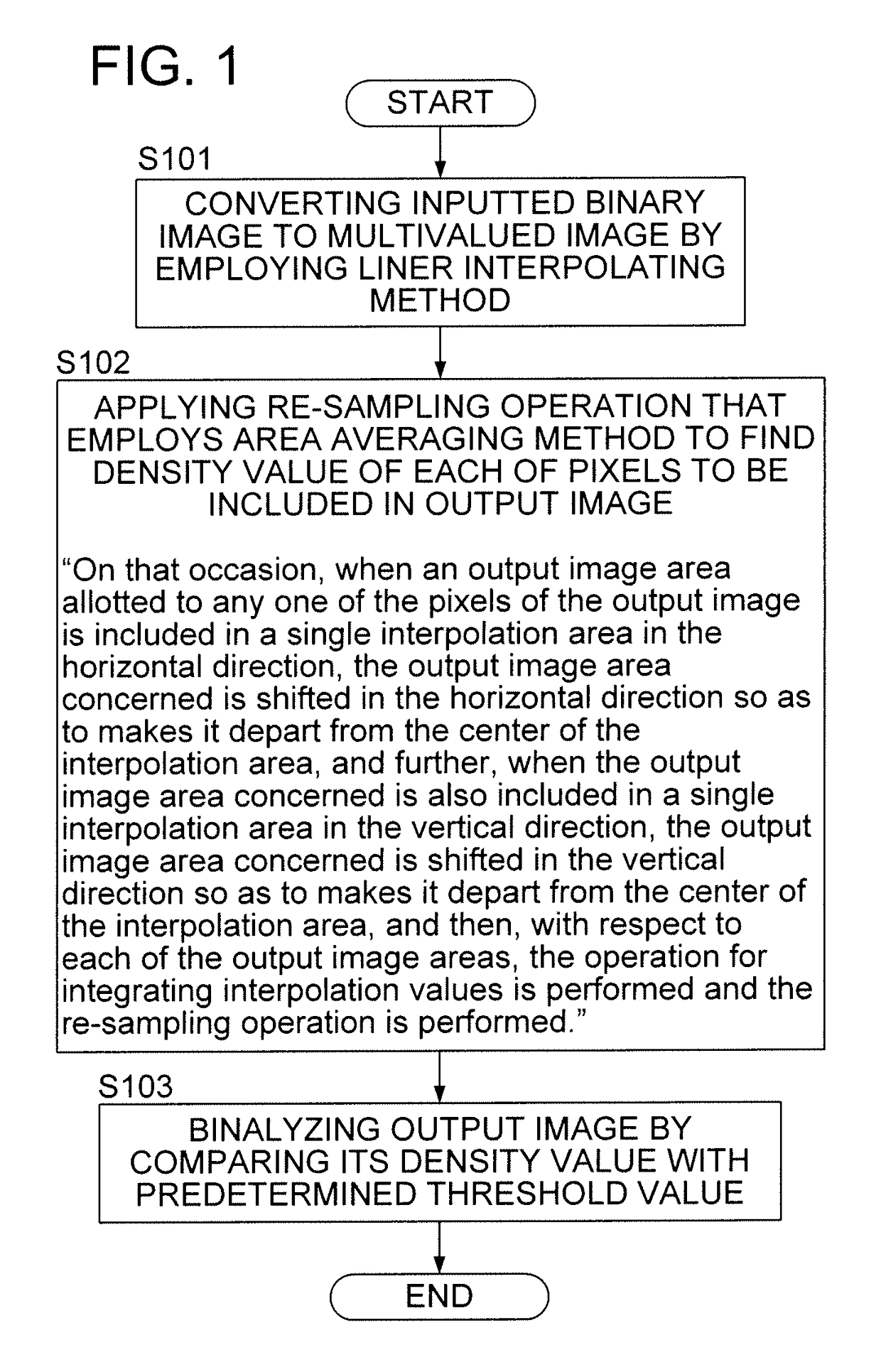
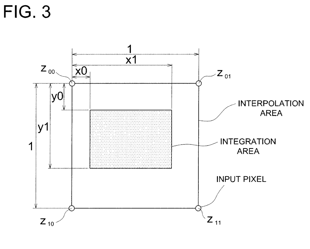
[0050]FIG. 1 shows a flowchart roughly indicating an overall processing flow of the resolution conversion method embodied in the present invention as the first embodiment. Although the processing flow shown in FIG. 1 is fundamentally the same as that described in the “BACKGROUND OF THE INVENTION” referring to FIG. 15, the processing flow shown in FIG. 1 is different from that indicated in FIG. 15 on the point that, when an output pixel area (pixel area of the output pixel) is included in a single interpolation area with respect to each of the horizontal direction and the vertical direction, an operation for integrating interpolation values is performed after the output pixel area is made to be shifted.

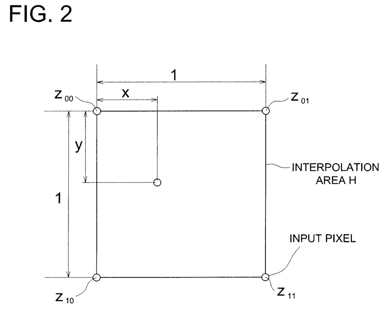
[0051]Initially, a density value (interpolation value) at an arbitral position between pixels of the input image, serving as the inputted binary image represented in the dot-matrix format, is found by employing the liner interpolating method, so as to convert the inputted binary image ...

second embodiment

[0072]Next, second embodiment will be detailed in the following.

[0073]FIG. 8 shows a flowchart roughly indicating an overall processing flow of the resolution conversion method embodied in the present invention as the second embodiment. Although the processing flow shown in FIG. 8 is fundamentally the same as that shown in FIG. 1, the processing flow shown in FIG. 8 is different from that indicated in FIG. 1 on the point that, when the output pixel area crosses over a plurality of input pixel areas P with respect to each of the horizontal direction and the vertical direction, an operation for integrating interpolation values is performed in Step S202 after the output pixel area is made to be shifted so that the concerned output pixel area approaches the center of a single input pixel area P. In this connection, the operation to be performed in Step S201 is the same as that in Step S101, and the operation to be performed in Step S203 is the same as that in Step S103.

[0074]Initially, ...

third embodiment

[0086]Next, the third embodiment will be detailed in the following.

[0087]According to the third embodiment, it becomes possible to cope with the resolution conversion processing, which employs an integer magnification factor, more appropriately than ever. In each of the first and second embodiments, as indicated in the schematic diagram shown in FIG. 17, the input image and the output image are superimposed (corresponded) with each other so as to make the center positions of pixel areas positioned at the four corners of the input image and those of the output image respectively coincide with each other. If the high-resolution conversion processing, which employs an integer magnification factor, is applied to the input image in the abovementioned mode, and for instance, if the integer magnification factor is set at two times of the input image, the phase relationships shown in FIG. 19 emerge all over the output image, resulting in a tendency to generate the thickness instability (or ...


PUM


Abstract

Disclosed is a resolution conversion method, which makes it possible not only to acquire a diagonal edge that is smoothed without causing any unevenness all over the image, but also to stably reproduce a thin line having a thickness corresponding to its original thickness, irrespective of an integer multiple or a non-integer multiple of the magnification factor to be employed for enlarging an original image, when the high-resolution conversion processing is applied to a binary image represented in the dot-matrix format. An operation for integrating the interpolation value with respect to the area of the input pixel is implemented after the output pixel area is shifted in a horizontal direction and / or a vertical direction so as to make the output pixel area depart from a center of the interpolation area, when the output pixel area is included in a single interpolation area in the horizontal direction and / or a vertical direction.

Description

[0001]This application is based on Japanese Patent Application NO. 2008-183182 filed on Jul. 14, 2008, with Japan Patent Office, the entire content of which is hereby incorporated by reference.BACKGROUND OF THE INVENTION[0002]The present invention relates to a resolution conversion method for converting a resolution of a binary image represented in the dot-matrix format.[0003]In the technical field of the resolution conversion of an image, the liner interpolating method (for instance, set forth in Tokkaihei 5-219360, Japanese Non-Examined Patent Publication) and the area averaging method (for instance, set forth in Tokkaihei 5-40825 and Tokkai 2006-270707, both Japanese Non-Examined Patent Publication) are generally employed for this purpose. With respect to the binary image, after the resolution conversion processing is completed, the binarizing processing is further applied to each of the pixels included in the image concerned, by comparing densities and threshold values of the pi...

Claims


Application Information

Patent Timeline
Patent Type & Authority Patents(United States)
IPC IPC(8): G06K9/40
CPCG06T3/4007
Inventor KAWABE, TORU
Owner KONICA MINOLTA BUSINESS TECH INC
Learn More