Optical reproducing device and optical memory medium

a reproducing device and optical memory technology, applied in the field of optical reproducing devices and optical memory media, can solve the problems of increasing the proportion of noise signals included in the reproduced data, increasing the probability of reading errors, and too large aperture formed on the magneto-optical disk

Inactive Publication Date: 2005-01-25
SHARP KK
View PDF25 Cites 11 Cited by
  • Summary
  • Abstract
  • Description
  • Claims
  • Application Information

AI Technical Summary

Benefits of technology

The first object of the present invention is to provide an optical reproducing device capable of precisely calculating the quantity of a reproducing signal obtained from an optical memory medium, and, based on the amplitude value of that reproducing signal quantity, precisely controlling reproducing power, and to provide an optical memory medium to be reproduced by this optical reproducing device.
In this way, the foregoing structure can always maintain a reproducing power capable of producing a reproducing signal of a predetermined signal quantity. Consequently, the frequency of reading errors such as crosstalk can be reduced, and stable reproducing is enabled.
Further, in the foregoing structure, the control signal output section detects a mean value of the reproducing signal quantity, and produces the first control signal on the basis of this mean value. Accordingly, the first control signal reflects the actual value of the reproducing signal quantity with great accuracy. Accordingly, the reproducing power control section is enabled to control the reproducing power of the reproducing signal production section with great accuracy.
Accordingly, with the foregoing structure, even if the timing of sampling for producing the digital signals for demodulation differs from the timing of sampling for producing the digital signals suited to reproducing power control, it is possible to perform accurate reproducing power control and demodulation with a low error rate.

Problems solved by technology

If reproducing power is much stronger than the optimum level, the aperture formed on the magneto-optical disk becomes too large.
Consequently, output of reproducing signals from tracks adjacent to the track being reproduced (crosstalk) is increased, the proportion of noise signals included in the reproduced data increases, and reading errors are more likely to occur.
Accordingly, reading errors are more likely to occur in this case as well.
For this reason, the amplitude ratio calculated from these amplitude values is not sufficiently accurate, and thus there is a large error in control of reproducing power in this recording and reproducing device.
However, drawbacks of this reproducing device include the following.
Accordingly, a drawback of this structure is that, if A / D conversion is performed with a timing suited to PR(1,2,1)ML demodulating, it is difficult to perform reproducing power control.
In this way, conventional structures have the problem that, when the optimum sampling timing for data reproducing (which is determined by the combination of the PRML demodulating method and the modulation method) does not conform with the optimum sampling timing for reproducing power control, accurate reproducing is difficult.

Method used


Image

  • Optical reproducing device and optical memory medium
  • Optical reproducing device and optical memory medium
  • Optical reproducing device and optical memory medium

Examples


first embodiment

[First Embodiment]

The first embodiment of the present invention will be explained below.

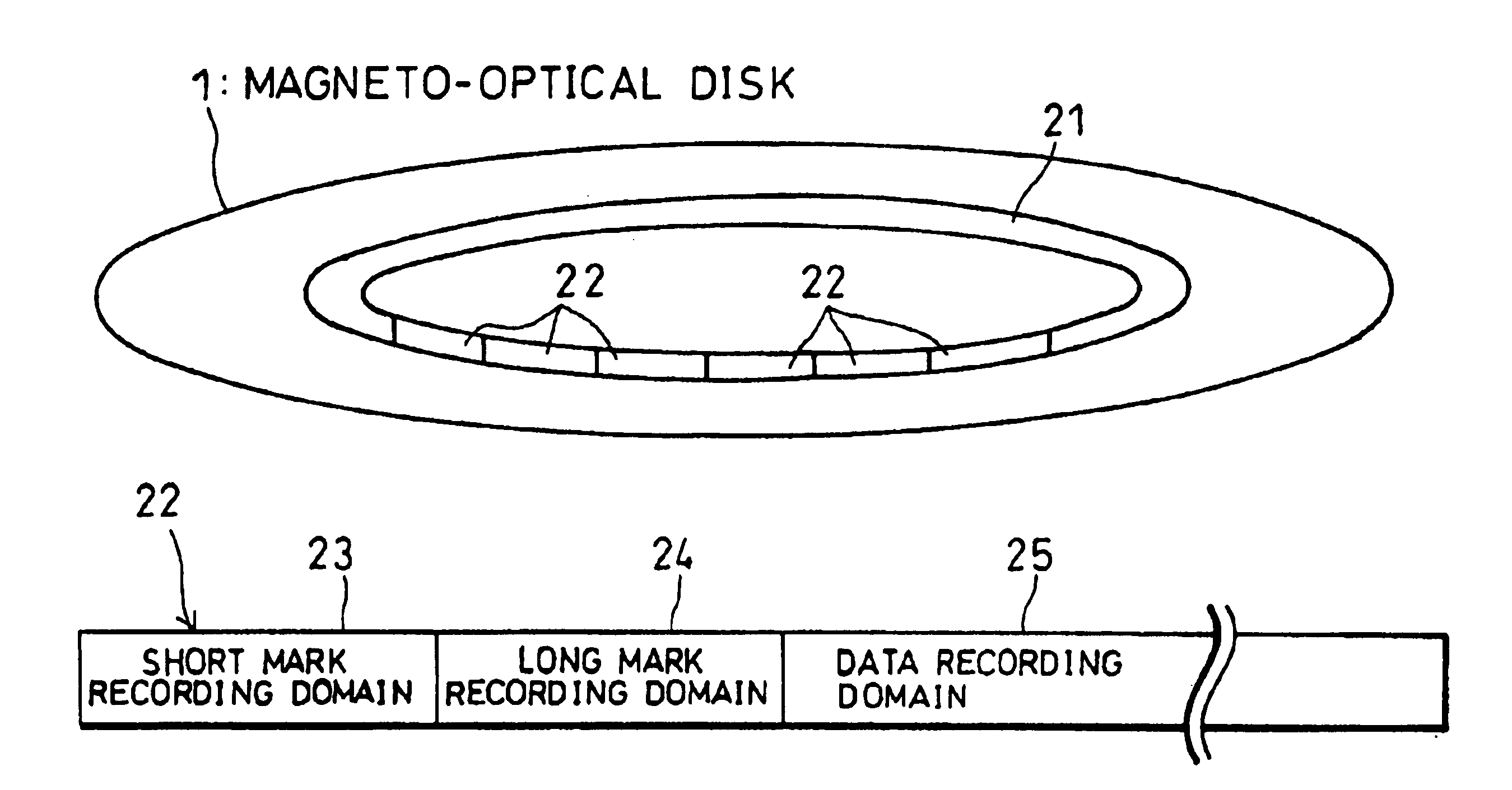
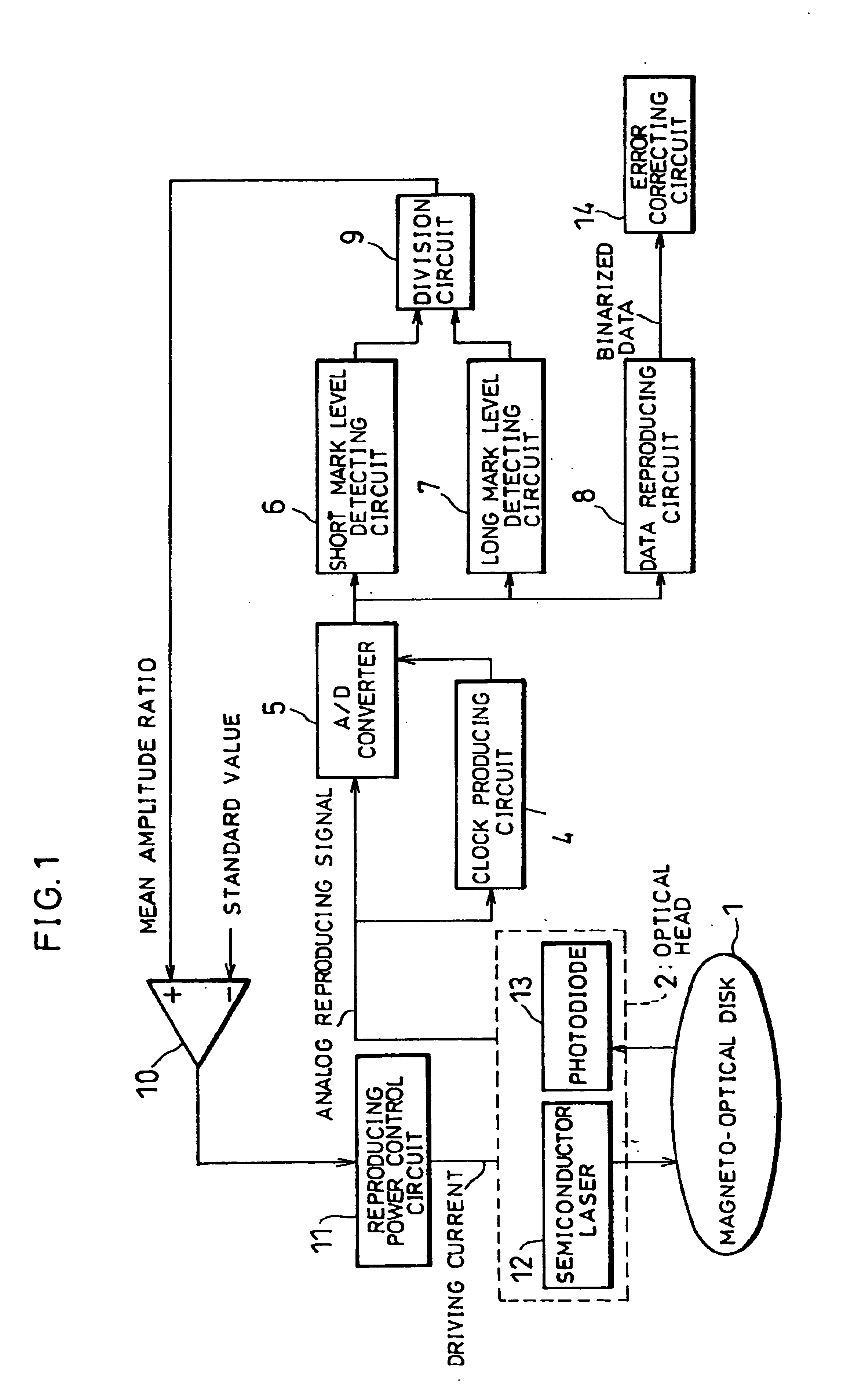
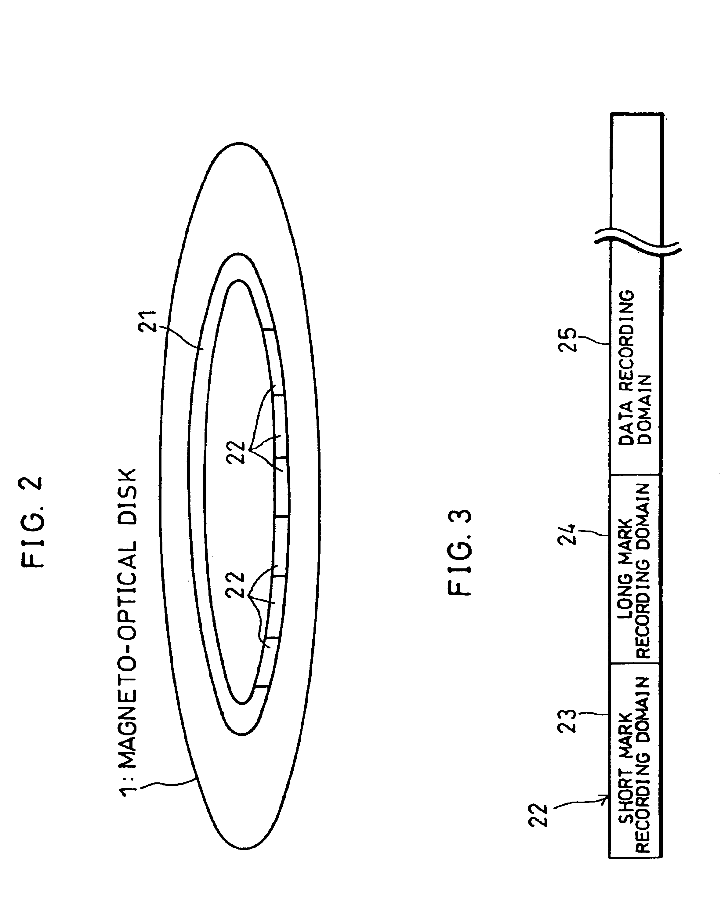
FIG. 1 is an explanatory drawing showing the structure of a magnetic ultra high resolution optical reproducing device (hereinafter referred to as “the present reproducing device”). As shown in the Figure, the present reproducing device is made up of an optical head 2, a clock producing circuit 4, an A / D converter 5, a short mark level detecting circuit 6, a long mark level detecting circuit 7, a data reproducing circuit 8, a division circuit 9, a differential amplifier 10, a reproducing power control circuit 11, and an error correcting circuit 14. Further, the magneto-optical disk 1 shown in FIG. 1 is an optical memory medium to be reproduced by the present reproducing device.

Prior to explaining the structure of the present reproducing device, the structure of the magneto-optical disk 1 will first be explained. In the magneto-optical disk 1 various data is recorded by (1,7)RLL (Run Length Limited...

second embodiment

[Second Embodiment]

The second embodiment of the present invention will be explained below.

FIG. 19 is an explanatory drawing showing the structure of a magnetic ultra high resolution optical reproducing device (hereinafter referred to as “the present reproducing device”). As shown in the Figure, the present reproducing device is made up of an optical head 62, an identification data reproducing circuit 64, a first clock producing circuit 65, a second clock producing circuit 66, a clock selecting circuit 67, an A / D converter 68, a PRML demodulating circuit 69, an amplitude ratio detecting circuit 70, a differential amplifier 71, and a reproducing power control circuit 72. Further, the magneto-optical disk 61 shown in FIG. 19 is an optical memory medium to be reproduced by the present reproducing device.

First, the structure of the magneto-optical disk 61 will be explained. The magneto-optical disk 61 is provided with a reproducing layer and a recording layer, and is a magnetic ultra hig...

third embodiment

[Third Embodiment]

The following will explain the third embodiment of the present invention. Members having functions equivalent to those of the second embodiment above will be given the same reference symbols, and explanation thereof will be omitted.

FIG. 26 is an explanatory drawing showing the structure of an optical reproducing device according to the present embodiment (hereinafter the “present reproducing device”). As shown in the Figure, instead of the identification data reproducing circuit 64, the first clock producing circuit 65, the second clock producing circuit 66, the clock selecting circuit 67, the A / D converter 68, and the amplitude ratio detecting circuit 70 of the optical reproducing device according to the second embodiment above, the present reproducing device is provided with a doubled clock producing circuit 101, an A / D converter 102, a signal separating circuit 103, a long / short mark extracting circuit 104, and an amplitude ratio detecting circuit 105.

Further, t...


PUM

PropertyMeasurementUnit
poweraaaaaaaaaa
poweraaaaaaaaaa
lengthaaaaaaaaaa

Abstract

An optical reproducing device according to the present invention detects mean amplitude values of short marks and long marks, which are recorded marks for reproducing power control, by means of a short mark level detecting circuit and a long mark level detecting circuit. Then a differential amplifier compares a ratio between these two mean amplitude values with a standard value, and outputs the result of this comparison. Thereafter, a reproducing power control circuit controls reproducing power of a semiconductor laser such that the absolute value of this comparison result is reduced. Since mean values of the amplitude values of the short marks and long marks are detected, the detection results are very accurate, and the precision of control of reproducing power can be greatly improved.

Description

FIELD OF THE INVENTIONThe present invention relates to an optical reproducing device and an optical memory medium, and in particular to an optical reproducing device which controls the quantity of light of a light beam projected onto an optical memory medium so as to bring close to a predetermined value the quantity of a reproducing signal from recorded marks recorded in the optical memory medium, and to an optical memory medium to be reproduced by this optical reproducing device.BACKGROUND OF THE INVENTIONIn magneto-optical disk devices which use the magnetic ultra high resolution method, a magneto-optical disk is used which is provided with a recording layer and with a reproducing layer having in-plane magnetization. In this type of magneto-optical disk device, during reproducing, a light beam is projected onto the reproducing layer side of the magneto-optical disk. Then, part of the area of the reproducing layer within the light beam spot is heated to above a predetermined temper...

Claims


Application Information

Patent Timeline
Patent Type & Authority Patents(United States)
IPC IPC(8): G11B11/105G11B7/013G11B27/30G11B11/00G11B7/125G11B7/007G11B7/005G11B7/00
CPCG11B7/00745G11B7/013G11B27/3027G11B11/10515G11B7/126G11B7/005G11B11/10595
Inventor OKUMURA, TETSUYAFUJI, HIROSHI
Owner SHARP KK
Why Eureka
Try Eureka