Cover plate for concealed sprinkler

a cover plate and sprinkler technology, applied in fire rescue, spray nozzles, spray apparatus, etc., can solve the problems of reducing the ability of the cover plate, and achieve the effect of reducing the response time of the sprinkler and low profil

Inactive Publication Date: 2002-09-19
VIKING
View PDF7 Cites 26 Cited by
  • Summary
  • Abstract
  • Description
  • Claims
  • Application Information

AI Technical Summary

Benefits of technology

[0008] According to one aspect of the invention, a concealed sprinkler head includes a thermally sensitive trigger assembly, a housing having a mounting surface and a central opening in fluid communication with the thermally sensitive trigger assembly, and a cover plate including a body member mounted to the mounting surface and having a periphery. The periphery has at least one passageway section and an adjacent periphery section adjacent the passageway section, with the passageway section disposed further from the mounting surface then the adjacent periphery section. A cover plate configured with at least one passageway section formed along the periphery provides an effective structure for enabling the passage of air towards the sprinkler head and thus decreases sprinkler response time while maintaining an aesthetically appealing, low profile appearance.
[0009] According to another aspect of the invention, a concealed sprinkler head includes a thermally sensitive trigger assembly, a housing with an annular flange and a central opening in which the thermally sensitive trigger assembly is positioned, and a cover plate having a body member formed with a periphery and a center. At least one mounting tab extends from the periphery, towards the center, and is attached to the annular flange by a fusible material. At least a section of the periphery is configured to permit the passage of air into the central opening and towards the thermally sensitive trigger assembly. Configuring the peripheral region of a cover plate to permit heated air to flow towards the sprinkler head results in greater sensitivity to the sprinkler head, while the at least one mounting tab provides a facile, reliable attachment structure.
[0010] According to yet another aspect of the invention, the cover plate includes a body member having at least one undulation formed therein. The undulation forms a passageway section at the periphery of the body member and provides an aesthetically appealing design, while enabling heated air to reach the thermally sensitive trigger assembly, and in consequence, increase the response time thereof.
[0012] According to a further aspect of the invention, a concealed sprinkler head comprises a sprinkler body with a central orifice, a deflector movably mounted to the sprinkler body, a sealing assembly for sealing the outlet, and a thermally sensitive trigger assembly configured to releasably urge the sealing assembly into engagement with the outlet of the central orifice. A housing is attached to the sprinkler body and has a central opening and a bottom extending beyond the outlet. The bottom is formed with an annular flange having at least one contact section depending below the annular flange. A cover plate includes at least one mounting section having a contact member. The contact member enables the cover plate to be attached to the annular flange such that in the assembled position, the at least one contact section is in substantial registry with the contact member. The cover plate has a periphery formed with at least one passageway section configured to enable air to travel between the passageway section and the bottom of the housing and towards the thermally sensitive trigger assembly. The registry of the contact member with the contact section depending from of the annular flange provides secure attachment of the annular flange to the cover plate, while the cover plate enables heated air to travel therethrough and contact the thermally sensitive trigger assembly, thereby decreasing response time.

Problems solved by technology

These airway openings, however, draw attention to the cover plate and diminish the cover plate's ability to perform its function of providing an aesthetic cover that does not visually detract from the ceiling or sidewall in which the sprinkler head is positioned.

Method used


Image

  • Cover plate for concealed sprinkler
  • Cover plate for concealed sprinkler
  • Cover plate for concealed sprinkler

Examples


Embodiment Construction

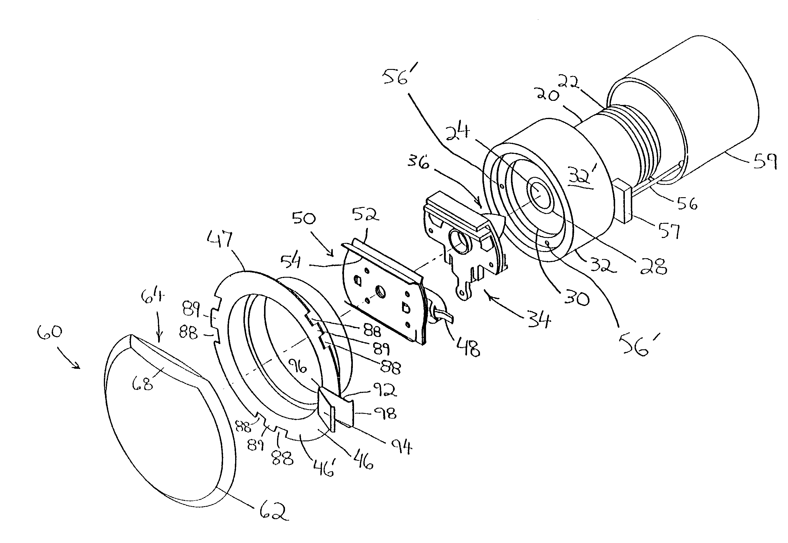
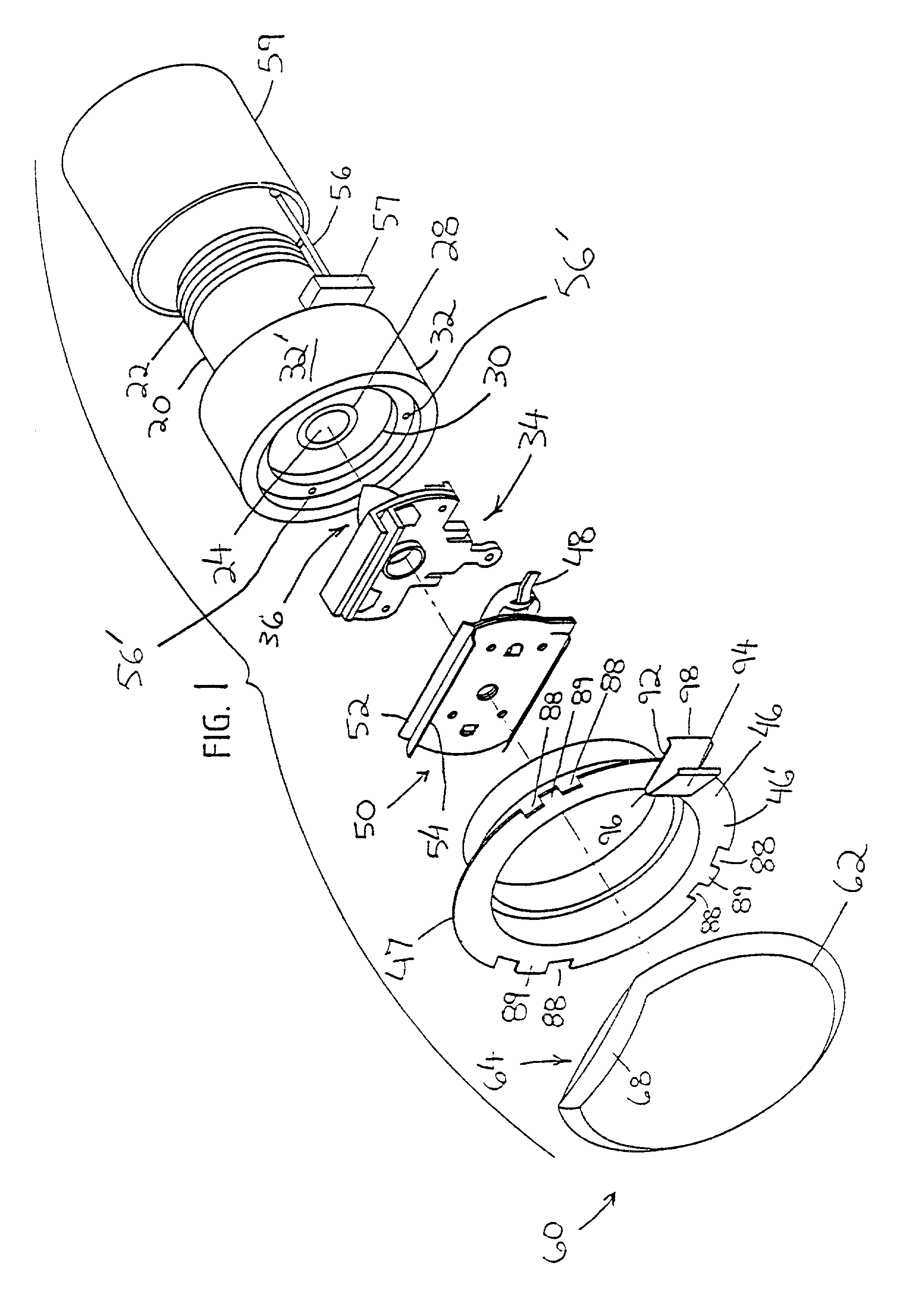
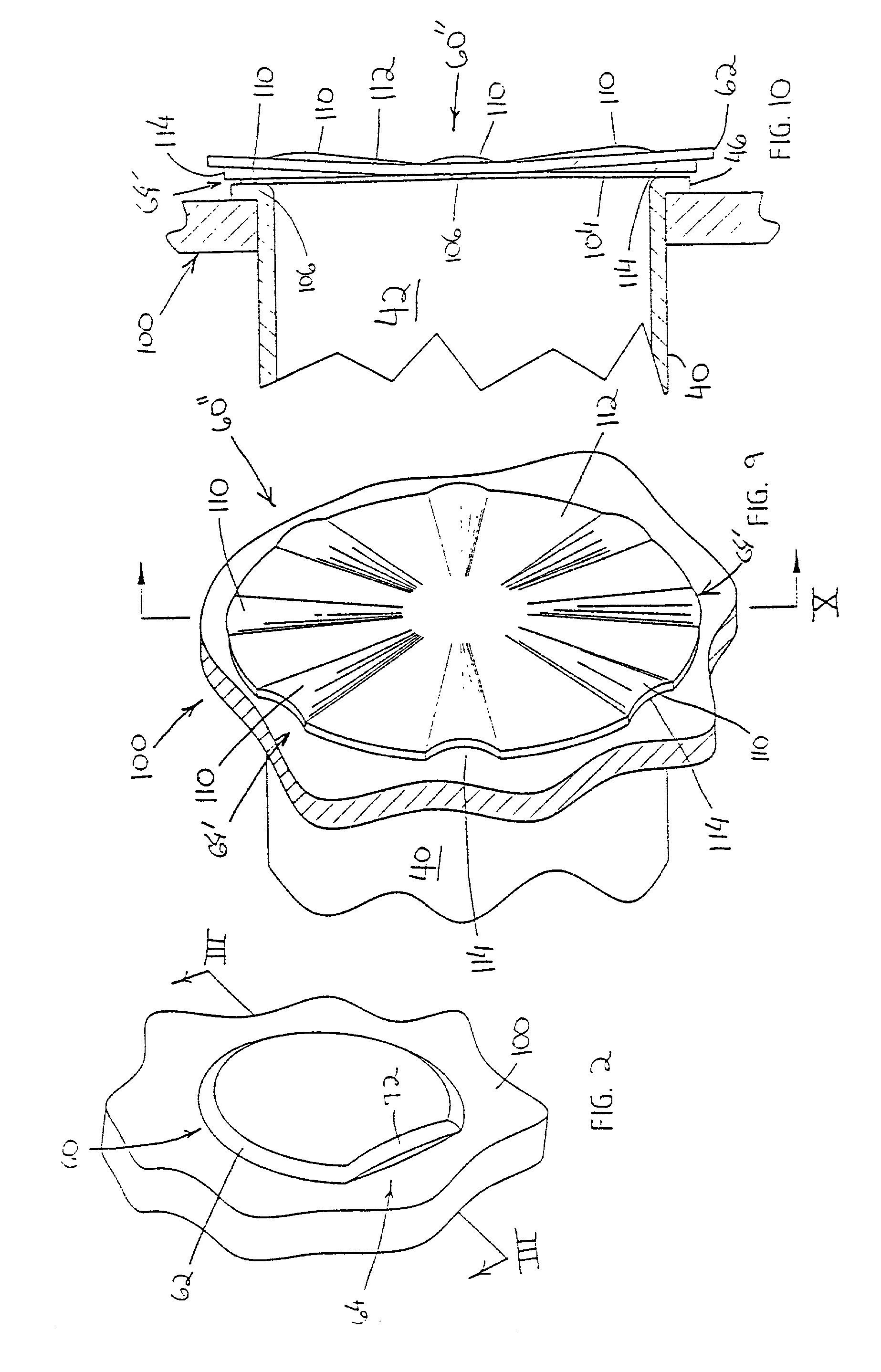
[0033] The present invention is directed to a unique cover plate for use in conjunction with a concealed or recessed sprinkler head. The cover plate of the present invention permits heated air to travel therethrough and impact the thermally sensitive trigger assembly to thereby increase the response time of the recessed sprinkler head, while maintaining a low profile, sleek aesthetic appearance which does not detract from the side wall or ceiling structure in which it is placed. The present invention will now be described with reference to the accompanying drawings wherein the like reference numerals correspond to like elements in the several drawings.

[0034] Referring now to the drawings, a concealed sprinkler head 10 normally contains a sprinkler body 20 having an upper section 22. Upper section 22 is externally threaded, allowing removable attachment to a fire extinguishing fluid supply line, normally in the form of a pipe, and positioned within a sidewall or ceiling. This pipe is...


PUM


Abstract

A cover plate for a concealed sprinkler includes a member having at least one passageway section enabling heated air to pass between the cover plate and the sprinkler housing and towards the sprinkler head to permit the timely activation of the sprinkler head. In one preferred form, the passageway section is defined by at least one lip projecting from the periphery of the cover plate, away from the sprinkler head. Alternatively, the cover plate may include a peripheral rim projecting away from the sprinkler head. In another preferred embodiment, the passageway section is defined by one or more undulations formed within the cover plate, each of which define a ridge at the periphery, enabling air to pass therethrough. The cover plate is substantially planar and includes a plurality of mounting tabs upon which a fusible material is applied to adhere the cover plate to the housing of the sprinkler head. The cover plate of the present invention increases the response time of the concealed sprinkler head while maintaining a low profile, discrete appearance so as not to detract from the sidewall or other structure upon which it is supported.

Description

BACKGROUND OF THE INVENTION[0001] The present invention relates generally to fire protection sprinkler systems, and more particularly, to a cover plate for a concealed fire sprinkler head.[0002] Sprinkler heads have long been used in automatic fire extinguishing systems in order to controllably disperse a fluid in order to suppress or extinguish a fire in a designated area. Typically, the fluid utilized in automatic fire extinguishing systems is water, however, systems have also been advanced to disperse other fire extinguishing fluids. In one common design, sprinkler heads include a solid metal base with a central orifice having an inlet connected to a pressurized supply of water or other fire extinguishing fluid. A deflector, spaced from the sprinkler body, alters the trajectory of the water in an optimum pattern when discharged from the central orifice. In many conventional sprinkler heads, the deflector is fixedly spaced from the outlet by a pair of rigid arms and mounted on a b...

Claims


Application Information

Patent Timeline
Patent Type & Authority Applications(United States)
IPC IPC(8): A62C37/09
CPCA62C37/09
Inventor RETZLOFF, JAMES G.FRANSON, SCOTT T.
Owner VIKING
Why Eureka
Try Eureka