
Manually positioned wheel chocking apparatus

a technology of a chocking device and a man-made frame, which is applied in the field of vehicle restraints, can solve the problems of high relative pressure of the trailer frame, affecting the safety of the loader, and requiring excavation of the parking area

Inactive Publication Date: 2002-10-03
RITE HITE HLDG CORP
View PDF0 Cites 38 Cited by
  • Summary
  • Abstract
  • Description
  • Claims
  • Application Information

AI Technical Summary

Benefits of technology

[0013] In accordance with another aspect of the invention, a chocking apparatus for securing a vehicle in a parking space adjacent a loading dock is provided. The chocking apparatus includes a track secured adjacent the loading dock, (for example, secured to the driveway adjacent the parking space); and a movable chock including a surface for selective positioning within the parking space at a location for engaging a tire of the vehicle. The movable chock further includes an extension for selective positioning adjacent the parking space in operative engagement with the track. The extension has at least one pin sized to engage one of a plurality of bores in the track to substantially prevent the chock from moving in at least one direction relative to the track.
[0018] In accordance with another aspect of the invention, a chocking apparatus for securing a vehicle in a parking space adjacent a loading dock is provided. The chocking apparatus includes a track secured adjacent the loading dock, for example, secured to the driveway adjacent the parking space; and a movable chock including a surface for selective positioning within the parking space at a location for engaging a tire of the vehicle. The movable chock further includes an extension for selective positioning adjacent the parking space in operative engagement with the track. The apparatus is further provided with means for temporarily fixing the chock to the track to substantially prevent the chock from moving in at least one direction relative to the track.
[0028] In accordance with still another aspect of the invention, a chocking apparatus for securing a vehicle in a parking space adjacent a loading dock is provided. The apparatus includes a track secured adjacent the loading dock, for example, secured to the driveway adjacent the parking space. The track defines a recess. The apparatus also includes a movable chock including a surface for selective positioning within the parking space at a location for engaging a tire of the vehicle. The movable chock further includes an extension for selective positioning at least partially within the recess. In addition, the apparatus is provided with a frictional lock for securing the extension of the chock to the track to substantially prevent the chock from moving relative to the track.

Problems solved by technology

If the vehicle were not restrained, and the truck operator were to prematurely drive away from the loading dock, loading dock personnel or equipment could be trapped on the truck and / or injured, particularly if a person was exiting or entering the truck when the vehicle pulled away from the dock.
However, such chocks suffer from the disadvantage of requiring excavation of the parking area if the chock is being added to a pre-existing dock area.
Some prior art chocks of the this type have also been disadvantageous in that they tend to run high relative to the trailer frame.
In other words, when the chock moves out of the lowered positioned towards the chocked position, some chocks immediately rise to their full height and then run towards the tire thereby creating the risk of contact between the chock and vehicle parts or items suspended beneath the truck.
Some prior art chocks are disadvantageous in that they involve complex mechanical structures.
Such structures render these chocks costly to purchase and costly to maintain.
Other automatic prior art chocks have been disadvantageous in that they strike the wheel too low to adequately prevent movement of the vehicle.
Traditional portable chocks also suffer from the same deficiency--i.e. striking the wheel too low--and may also be disadvantageous as nothing holds the chock in place along the driveway, and they are thus subject to sliding over the driveway surface.

Method used


Image

  • Manually positioned wheel chocking apparatus
  • Manually positioned wheel chocking apparatus
  • Manually positioned wheel chocking apparatus

Examples


Embodiment Construction

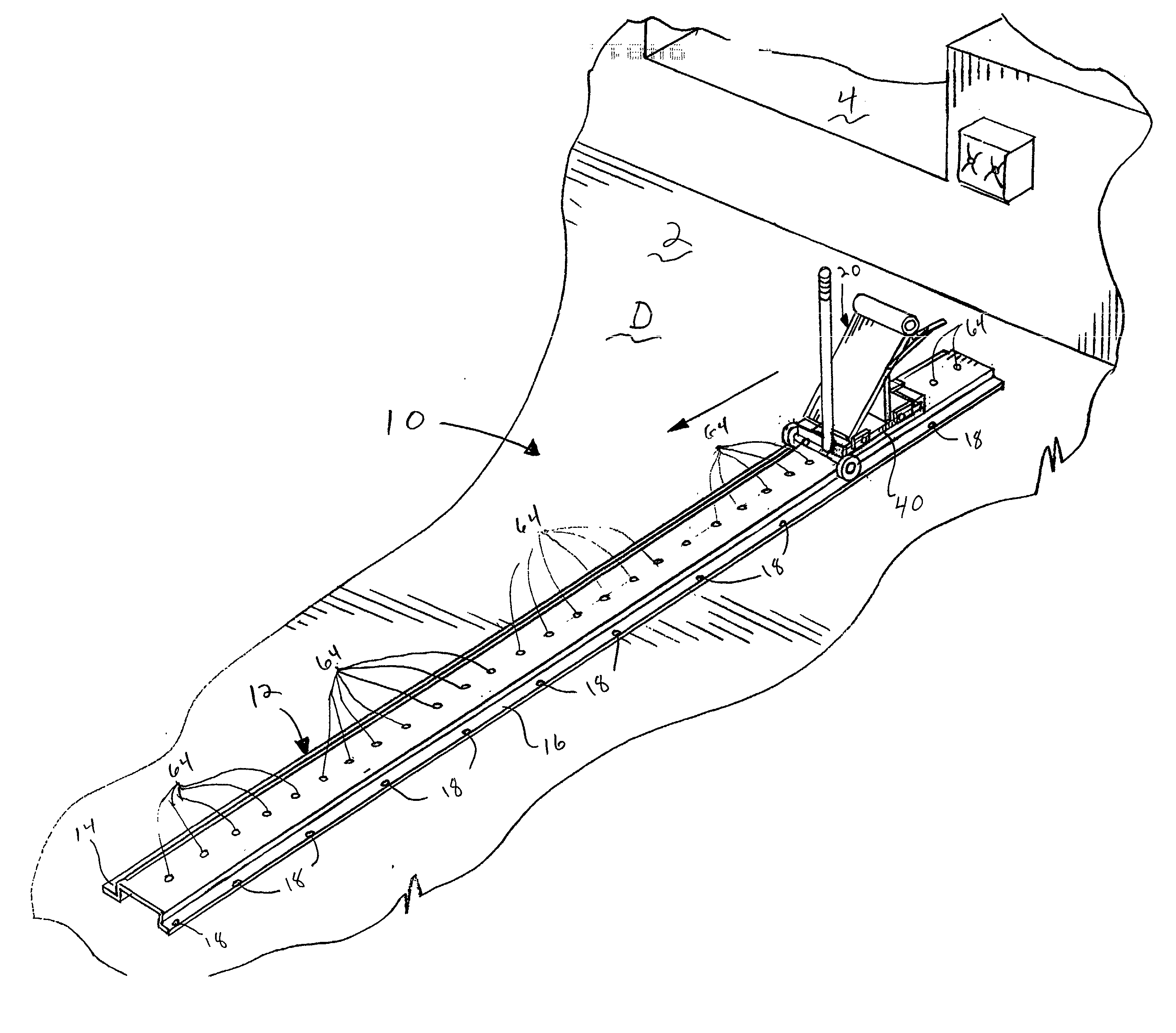
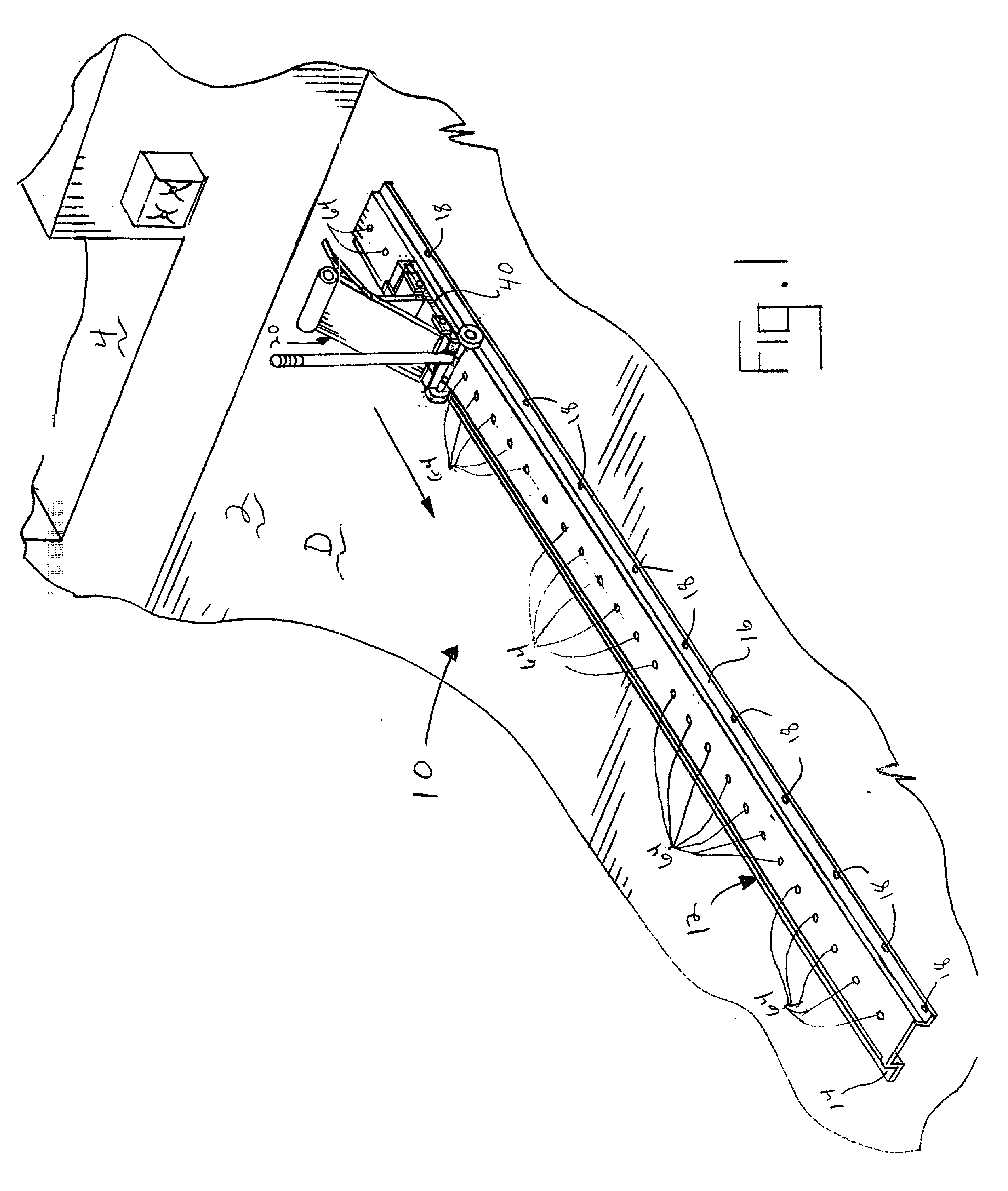
[0048] A manually positioned wheel chocking apparatus 10 constructed in accordance with the teachings of the invention is illustrated in FIG. 1. Although the wheel chocking apparatus 10 is shown being used on the driveway D adjacent a parking area 2 in front of a loading dock 4 on a warehouse or the like, persons of ordinary skill in the art will readily appreciate that the teachings of the invention are not limited to any particular environment of use. On the contrary, the teachings of the invention are applicable to any environment where restraining a vehicle is useful or desired.

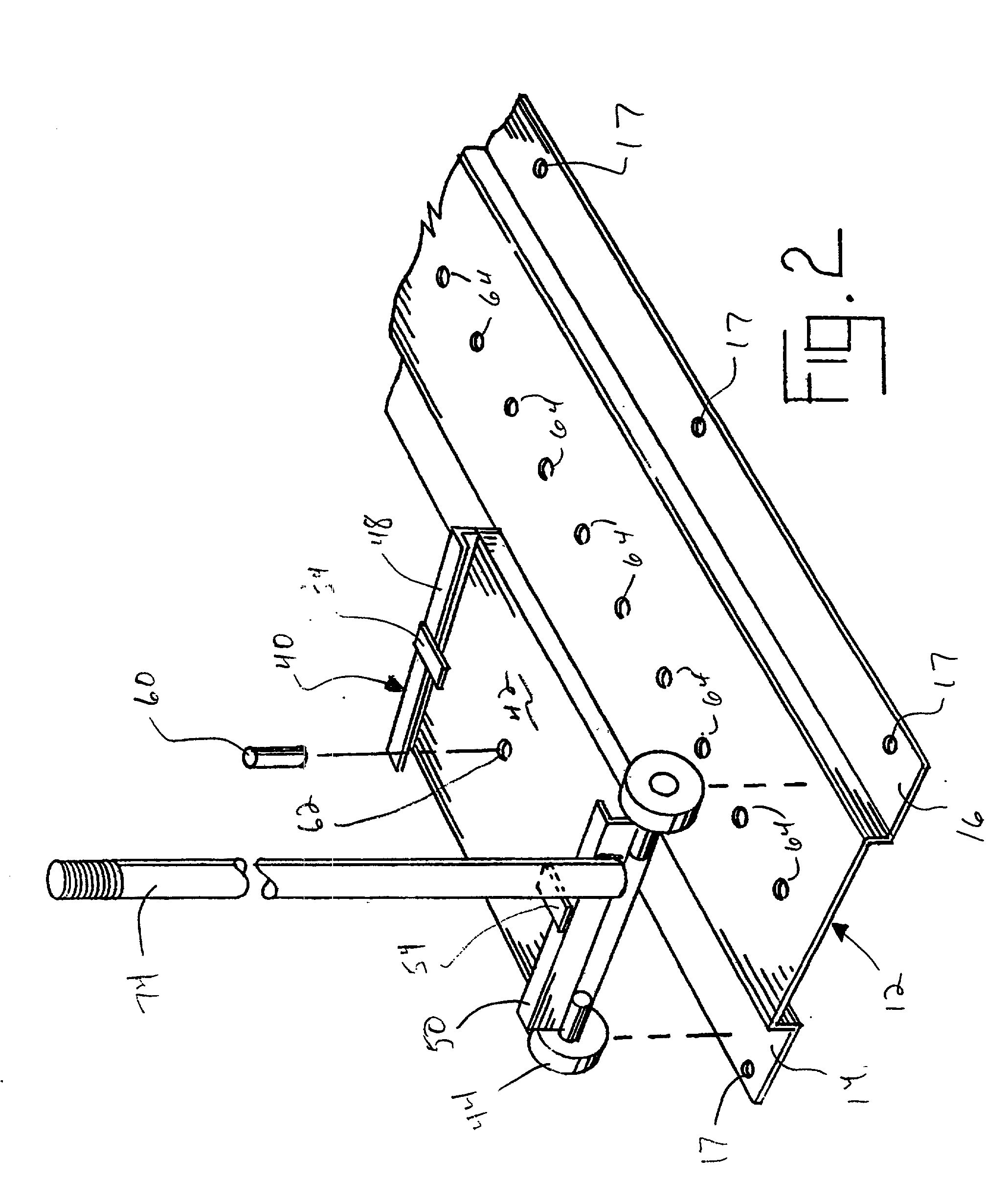
[0049] For the purpose of securing the chocking apparatus 10 in a predefined position, the apparatus 10 is provided with a rectangular, raised track 12. As shown in FIG. 1, the track 12 is secured adjacent the loading dock. In this representative example, this is achieved by securing the track to the driveway D adjacent and parallel to a parking area 2. While securing to the driveway is preferred, the tra...


PUM


Abstract

Manually positioned wheel chocking apparatus are disclosed. In a preferred embodiment, the chocking apparatus includes a track secured adjacent a parking area; a movable chock; and means for temporarily fixing the chock to the track to substantially prevent the chock from moving. The movable chock has a surface which can be selecidvely positioned within the parking space at a location for engaging a tire of a vehicle. It also includes an extension for operatively engaging the track. The fixing means may optionally comprise a pin sized to mate with a bore in a track or a, frictional lock, preferably constructed as an over-center toggle.

Description

FIELD OF THE INVENTION[0001] The invention relates generally to vehicle restraints and, more particularly, to manually positioned chocking apparatus for restraining a vehicle in a parking space or the like.BACKGROUND OF THE INVENTION[0002] The need to restrain vehicles in certain instances has long been known. For example, it has long been known that certain safety benefits can be achieved by securing a truck adjacent a loading dock during loading or unloading of that vehicle. If the vehicle were not restrained, and the truck operator were to prematurely drive away from the loading dock, loading dock personnel or equipment could be trapped on the truck and / or injured, particularly if a person was exiting or entering the truck when the vehicle pulled away from the dock.[0003] Many solutions to this problem have been proposed. For example, motorized vehicle restraints which book to the ICC bar of a trailer parked adjacent to a loading dock such as those sold by Rite-Hite Corp. and as ...

Claims


Application Information

Patent Timeline
IPC IPC(8): B65G69/00
CPCB65G69/005
Inventor HAHN, NORBERTSPRINGER, SCOTT L.
Owner RITE HITE HLDG CORP
Learn More