

Milk flow monitor and milker unit detacher
a technology of milk flow monitor and milker unit, which is applied in the direction of milking devices, catheters, animal husbandry, etc., can solve the problems of limited use, lack of monitoring of milk flow in dairy harvesting facilities, and failure to accommodate the unique characteristics of individual cows
Inactive Publication Date: 2002-10-17
GOMPPER BRION +2
View PDF0 Cites 30 Cited by
- Summary
- Abstract
- Description
- Claims
- Application Information
AI Technical Summary
Problems solved by technology
Presently, dairy harvesting facilities do not monitor milk flow to control a multitude of dairy facility operations.
Some facilities make limited use of milk flow data for use with automatic milker detachers that are controlled by milk meters, timers, or by an operator who monitors milking progress visually.
The current methods used to milk cows or detect the end of the milk cycle fail to accommodate the unique characteristics of individual cows.
While these variances in let-down curves have always been known to dairy farmers, no mechanisms or procedures have ever been developed to optimize milking for individual cows.
Fewer cows results in lower capital requirements, healthier herds, reduced manpower, and shorter milking times.
In large dairy herds it may be possible to use a programmable read-only-memory (PROM) milker controller or detacher to obtain acceptable yields from most of the cows, but many cows will not provide optimum yields under the "average" milking conditions that must be assumed in the PROM.
In small dairies, the cow-to-cow variations in milk flow curves will be more pronounced and finding an optimum milking cycle for most cows will be more difficult.
Thus, using any rigid milking standard or cycle cannot simultaneously optimize cow yields and cow health, nor can a simple operator interface that can override preprogrammed milking instructions, because the interface can not re-program the system.
The milk flow conditions through a milk flow meter do not necessarily indicate an ideal time to end the milk cycle for all cows or all dairies.
Further complicating matters is that there are varying degrees of wet milking dairy operators believe to be best.
Obviously, these conditions vary over time and no pre-programmed printed circuit board can possibly accommodate the infinite number of variable combinations that a particular automated detacher unit may be called upon to consider in any particular dairy to accommodate that particular dairy's needs.
This is less than desirable, because if a cow is left unattended during an extended override milking period, the cow can be unnecessarily stressed and teat damage can occur.
Automatic detachers lose their advantages when override abuses occur and the override can not be used to vary milking instructions.
Dairy throughput is also adversely affected by present detacher systems, that do not have the ability to deal with the large number of variables affecting milking production.
A system that milks each cow to completion can cause delays in throughput because some cows will be finished milking before others in their milking group, but no new cows are brought in until all the cows in that group have finished milking.
This delay is unnecessary when the last quarter, to one third of the milking cycle is a time of diminishing returns for milk production.
The data currently being collected is monitored on a regular basis, but milk production histories from a previous month, week, or even day will not provide complete and timely information about milking conditions or cow health.
Nor does such a milk production history provide information about milking cycle rates, daily changes in feed, weather, milking time of day, cow health, and so on.
No attempt is made to use it for real-time control of milking times, vacuum control, or optimizing milk yield.
Thus, prior data acquisition systems do not provide enough versatility to adjust to constantly changing factors affecting herd health and milking conditions.
Nonetheless, even these systems do not interact with other dairy components to modify milking conditions, such as pulsation rate and ratio for particular cows, or redistribute milk from sick cows to alternate storage or to waste.
However, no suggestion has been made to use milk monitoring as a central node or module upon which milking and diagnostics are optimized and other dairy system modules are subservient.
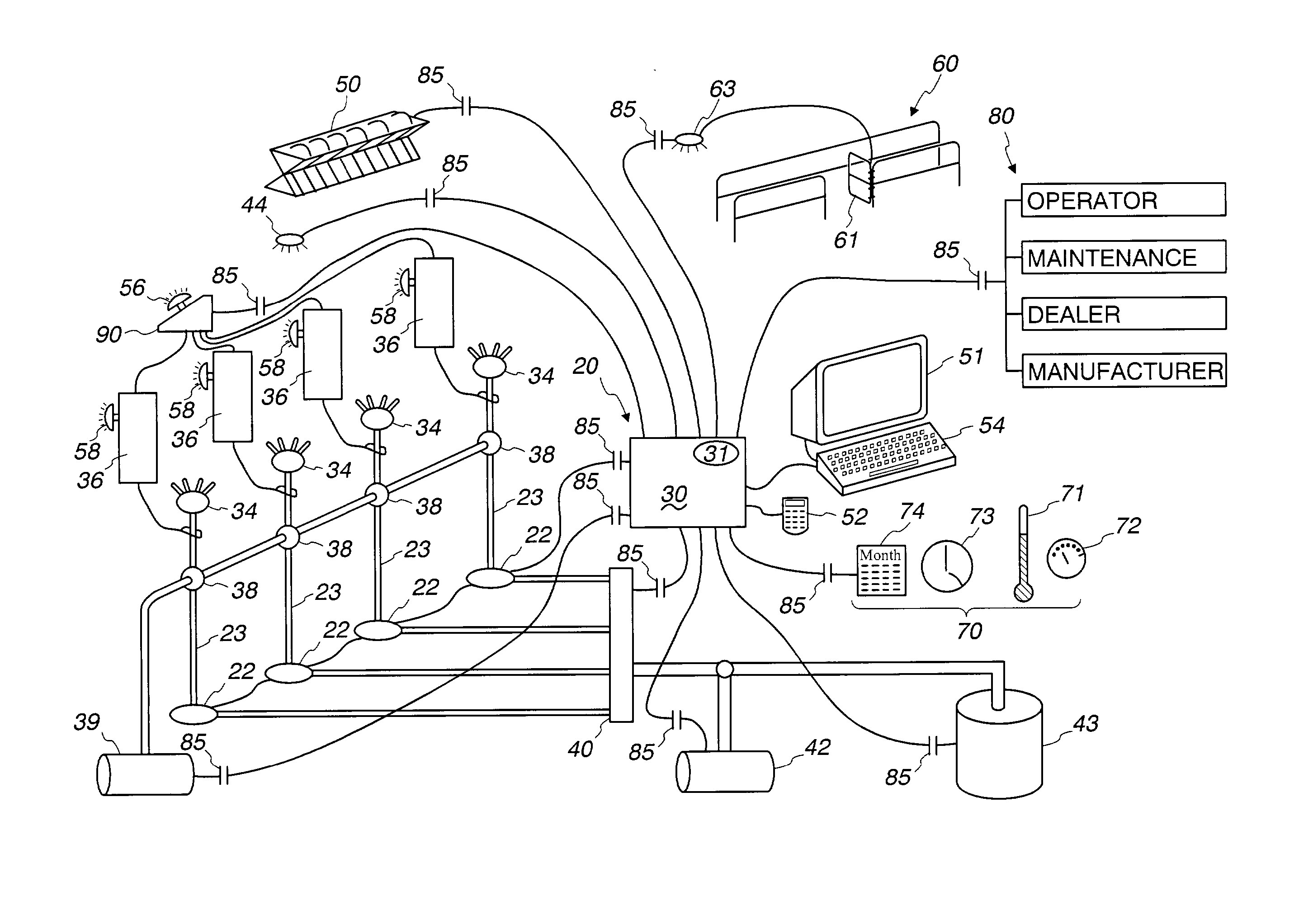
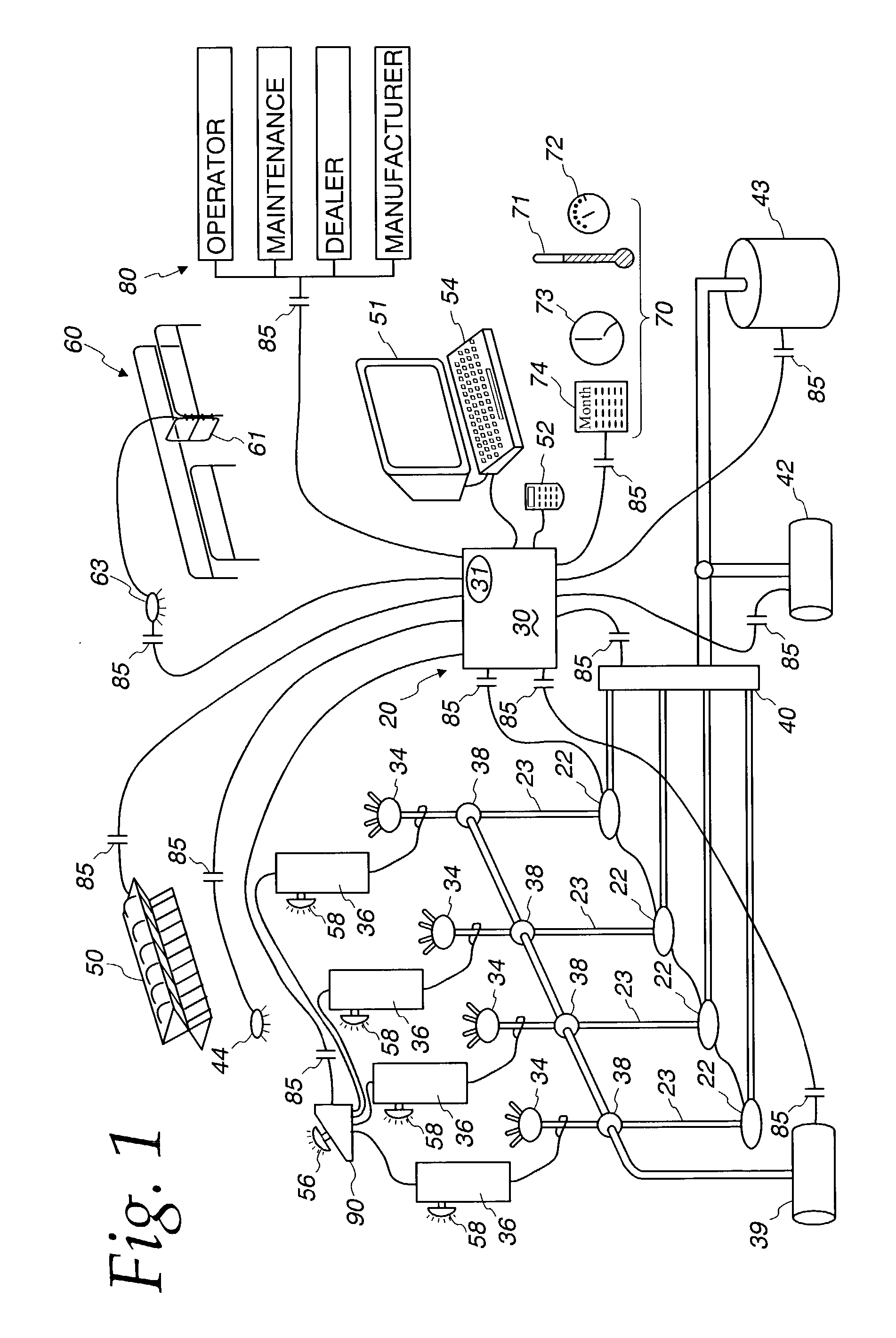
If a cow with severe mastitis, for example, were to be milked and the milk sent to a bulk tank 44, all of the milk in the bulk tank 44 could be contaminated and consequently lost.
This practice prevents harm to the first quarter milked because no additional milking vacuum is applied after milking is completed, which can cause teat damage.
Depleted herd milk production may indicate to operators and veterinarians that there are poor feed conditions or herd health.
Method used
View moreImage
Smart ImageViewing Examples

Examples
Embodiment Construction
is provided for clearness of understanding only and no unnecessary limitations therefrom should be read into the following claims.
Login to View More PUM
 Abstract
A milk monitor with a sensor positioned near the milker unit to monitor milk conditions and adjust a variety of dairy facility operations in response to milk conditions. The milk monitor is programmable to provide flexibility, real-time adjustment of dairy operations, and trend analysis and control to optimize milk production and herd health.
Description
[0001] This application is a continuation of U.S. application Ser. No. 09 / 161,836 filed Sep. 28, 1998, the disclosure of which is incorporated by reference herein.FIELD AND BACKGROUND OF THE INVENTION[0002] The present invention relates generally to a computer-implemented milk monitor for a dairy harvesting facility, and more particularly, to a milk sensor for monitoring the condition of milk from livestock being milked and an activity-based controller that reacts to the milk condition by controlling dairy facility operating parameters. The sensor acquires data about the milk that is converted to signals that are converted by the activity-based controller to dairy system control parameters that: control milking times; warn operators of adverse milking conditions; interface with other dairy system modules such as vacuum systems, utilities, milk cooling and storage, and chemical dispensers; or are able to transfer data to archives for use by the dairy operator, equipment and maintenan...
Claims
Login to View More Application Information
Patent Timeline
 Patent Type & AuthorityApplications(United States)
IPC IPC(8): A01J5/01A01J5/017A01K11/00
CPCA01J5/01A01K11/006A01J5/017
InventorGOMPPER, BRIONKEEFFE, KEVINKULIG, STEVEN H.
OwnerGOMPPER BRION