

Method and apparatus for superfinishing tapered roller bearing
a tapered roller bearing and superfinishing technology, applied in mechanical equipment, superfinishing machines, manufacturing tools, etc., can solve the problems of increasing the frequency of superfinishing stone replacement, reducing operation efficiency, and increasing the waste of clamping parts
Inactive Publication Date: 2002-10-24
NSK LTD
View PDF0 Cites 12 Cited by
- Summary
- Abstract
- Description
- Claims
- Application Information
AI Technical Summary
Problems solved by technology
Therefore, when an outer ring having a small bore diameter is superfinished, it is necessary to use a short superfinishing stone that can be inserted into the inner periphery of the outer ring, which increases the frequency of replacement of the superfinishing stone, resulting in the lowered operation efficiency.
Also, a superfinishing stone requires a clamp portion which is not used and, therefore, in the case of a short superfinishing stone, the clamp portion to be wasted increases, which results in the uneconomical superfinishing stone.
Further, the interference of the superfinishing stone rear end portion with the non-working raceway surface of the outer ring not only, as described above, disables use of a long superfinishing stone but also provides an obstacle to realization of an automatic superfinishing stone feed-out mechanism which automatically feeds out the superfinishing stone depending on the consumption.
When a superfinishing stone is worn, the superfinishing stone is moved toward the working-side raceway surface and the working is still kept on; however, the superfinishing stone need to be replaced with a new one before the superfinishing stone cannot be held by the superfinishing stone clamp bolt.
Method used
View moreImage
Smart ImageViewing Examples

Examples
Embodiment Construction
88 85 31.5 18 17 17 3 2.4 2 0.4 (R59Z-7) (15-20) Example 2 40 36.5 26 11 10 17 3 8.5 4 0.12 (HR30203J) Example 3 62 57 28 14 13 17 3 4.3 2.9 0.23 (HR30206J) Example 4 80 74 28 16 15 17 3 2.4 2 0.4 (HR30208J) Example 5 65 60 28 14 13 17 3 2.4 2 0.4 (LM48510R) Example 6 40 36 21.5 11 9 17 3 8.5 4 0.12 (L11710R) (15-17) Examples 1-6 are manufactured by NSK Ltd. and reference characters within parentheses express designation
Login to View More PUM
| Property | Measurement | Unit |
|---|---|---|
| Angle | aaaaa | aaaaa |
| Mass | aaaaa | aaaaa |
| Mass | aaaaa | aaaaa |
Abstract
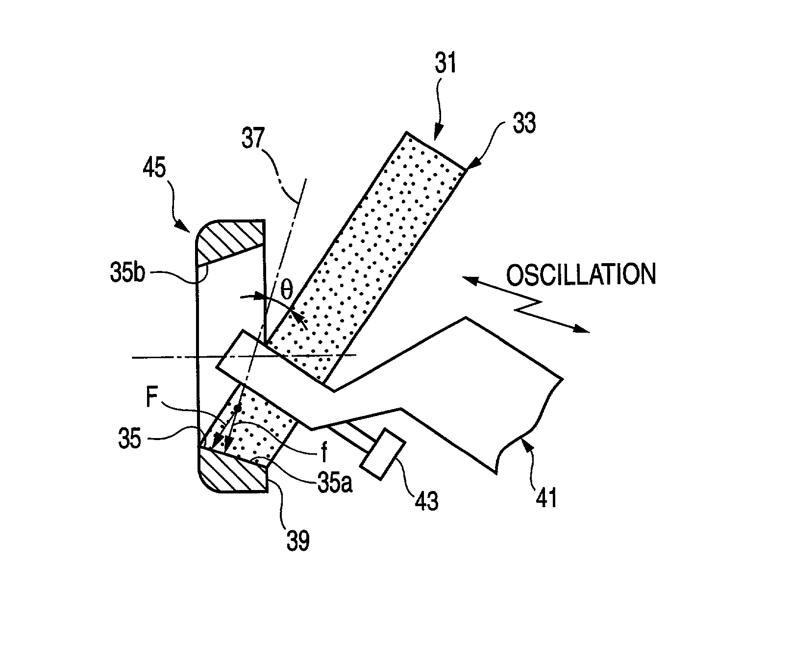
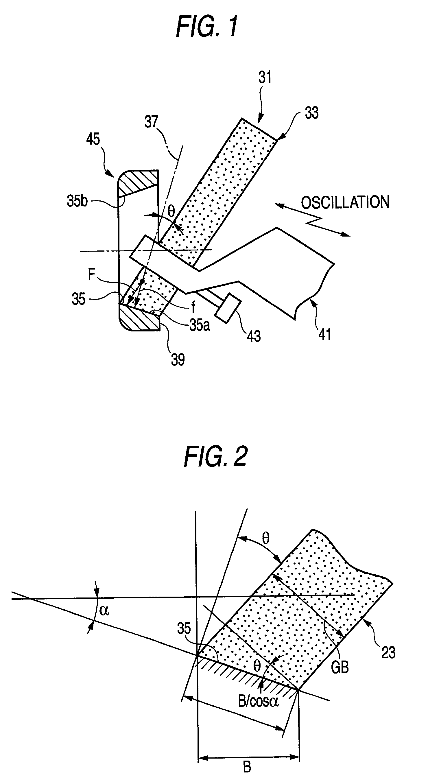
A superfinishing method of a tapered roller bearing, including the steps of: rotating an outer ring of the tapered roller bearing about a center axis thereof; inserting a straight-shaped superfinishing stone from a front face of outer ring; and slidingly contacting a leading end face of the superfinishing stone with a taper-shaped raceway surface formed in an inner peripheral surface of the outer ring to thereby superfinish the raceway surface. The superfinishing stone is inclined outwardly of the front face of outer ring with respect to a vertical line of the raceway surface.
Description
[0001] 1. Field of the Invention[0002] The present invention relates to a method and an apparatus for slidingly contacting a superfinishing stone with a raceway surface formed in an outer ring of a tapered roller bearing to thereby superfinish the raceway surface and, more particular, to an improved technology which can avoid an interference between the superfinishing stone and the outer ring.[0003] 2. Description of the Related Art[0004] Conventionally, to superfinish a raceway surface of an outer ring of the tapered roller bearing, for example, there is used such a superfinishing apparatus 1 as shown in FIG. 7. The superfinishing apparatus 1 includes a backing plate 5, a pair of pusher rollers 7 (only one of them is shown), a pair of shoes 9 (only the lower portion is shown), a superfinishing stone holder 13, a superfinishing stone clamp bolt 17, a pressurizing cylinder 21 and an oscillation table 23. The backing plate 5 causes an outer ring 3 to rotate. The pair of pusher rollers...
Claims
Login to View More Application Information
Patent Timeline
 IPC IPC(8): B24B49/10B24B5/14B24B19/06B24B35/00F16C19/36F16C33/64
CPCB24B5/14B24B19/06Y10T29/49693F16C19/364F16C33/64B24B35/00
InventorOZAKI, TAIFUKANO, TOMEOSUGIYAMA, TOORU
OwnerNSK LTD