Magnetic name plate assembly and connector therefor

a name plate and connector technology, applied in the direction of identification means, medals, display means, etc., can solve the problems of difficulty for users to remove the assembly from clothing, and the disengagement of the badge assembly from the garmen

Inactive Publication Date: 2002-10-24
REEVES
View PDF0 Cites 21 Cited by
  • Summary
  • Abstract
  • Description
  • Claims
  • Application Information

AI Technical Summary

Benefits of technology

[0007] In accordance with one aspect, there is provided a name plate assembly for use on a garment having a name plate and a connector which are magnetically attracted to each other, and which are disposed on opposite sides of a piece of clothing during use such that the clothing is sandwiched therebetween. The name plate assembly is removed from the garment by the user pressing the connector through the fabric, or by otherwise engaging the connector, for example by grasping and pulling on the connector. In this manner, the connector acts as a lever in order to break the magnetic connection between the name plate and the connector so that the name plate assembly may be easily removed from engagement with the article of clothing without excessive force.

Problems solved by technology

While effective in adhering the name plate assembly to a an article of clothing, it can be difficult for a user to remove the assembly from the clothing.
While generally effective, it has been found that the badge panels can become easily detached from each other by simply brushing against the outer panel of the badge assembly, which causes the badge assembly to disengage from the garment.

Method used


Image

  • Magnetic name plate assembly and connector therefor
  • Magnetic name plate assembly and connector therefor
  • Magnetic name plate assembly and connector therefor

Examples


first embodiment

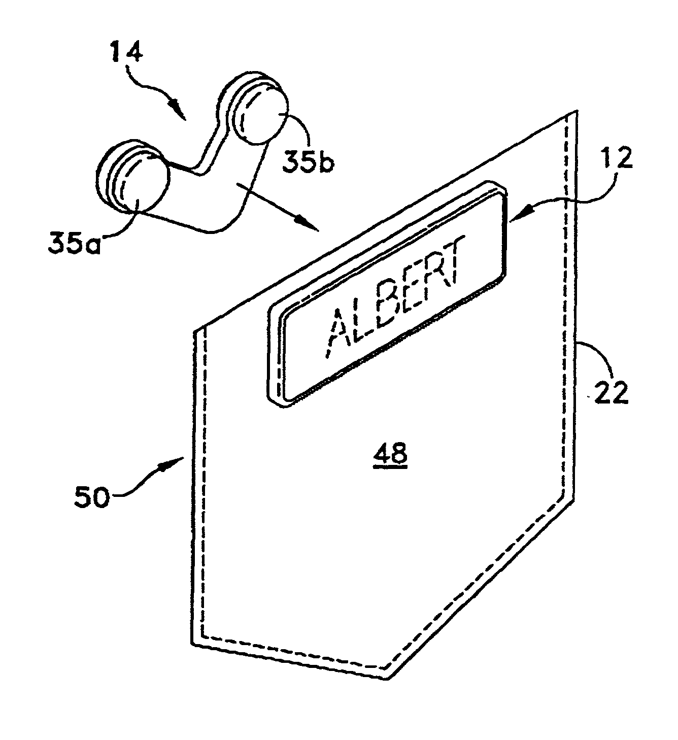
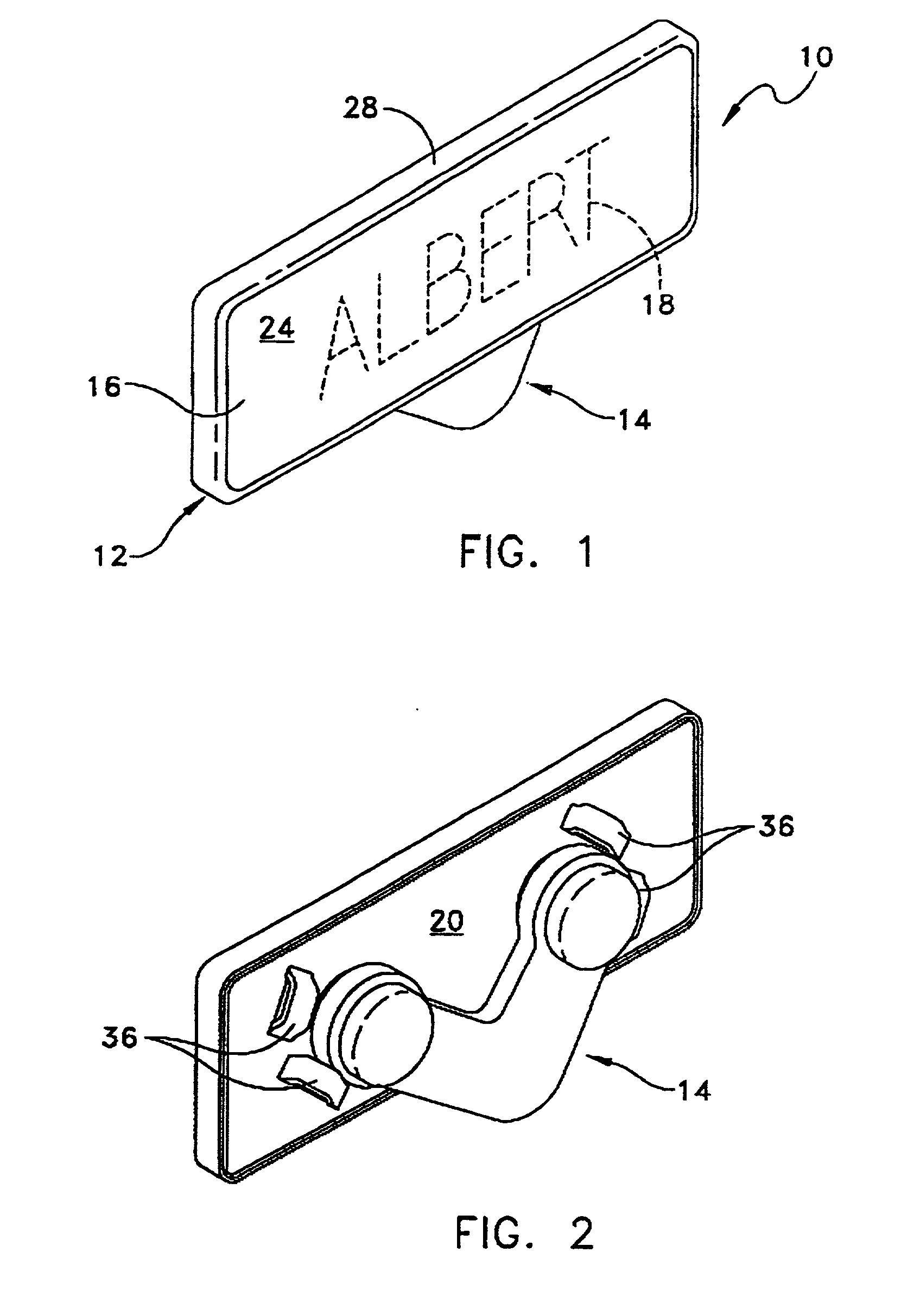
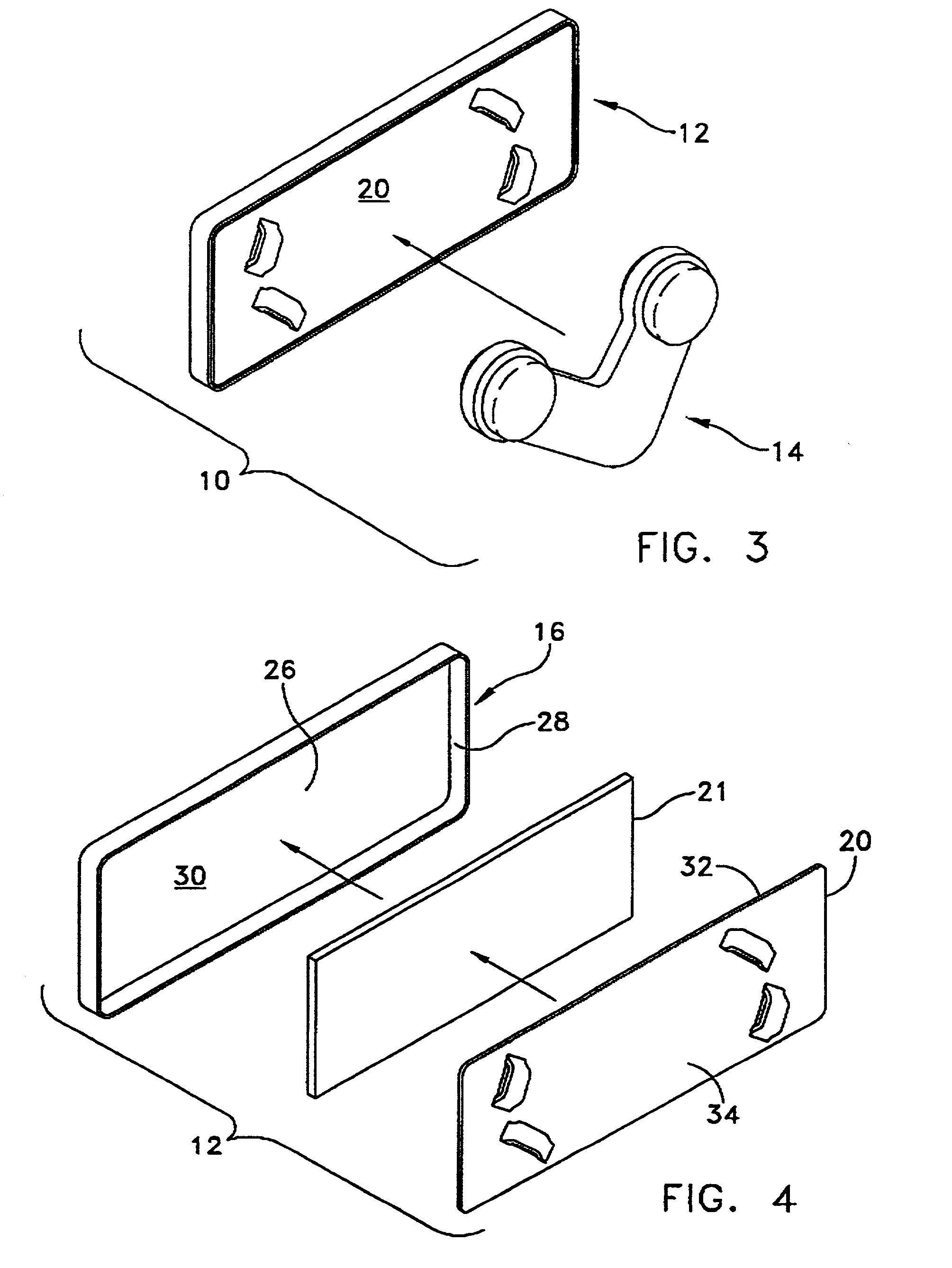
[0037] A magnetic name plate assembly 10 for attachment to an article of clothing according to the present invention is illustrated in FIGS. 1-9. The name plate assembly 10 preferably includes a name plate 12 and a connector 14 which are magnetically attracted to each other, and which are disposed on opposite sides of a piece of clothing during use such that the clothing is sandwiched therebetween.

[0038] The name plate preferably includes a face plate 16 for displaying indicia, such as a user's name 18, and a back plate 20 which is adapted to engage the article of clothing 22 (FIG. 8). The face plate 16 may be attached to the back plate 20 by adhesive, for example a strip of double sided adhesive tape 21. In the present embodiment, the face plate preferably includes a front surface 24 and a rear surface 26, with a lip 28 extending from the front surface and around a perimeter of the face plate. The lip defines a recess 30 for receiving the adhesive tape 21 and back plate 20 therein ...

third embodiment

[0043] Referring now to FIGS. 12-13, the name plate assembly is illustrated. In this embodiment, all parts which are the same, or similar to, corresponding parts of the previous embodiments are noted with the same two last numbers, but preceded by the numeral "2". Name plate assembly 210 includes a name plate 212 and a connector 214 which are magnetically attracted to each other. In this embodiment, the name plate 212 is substantially identical to the name plate described with respect to FIGS. 1-9. The connector 214 has been modified, such that connector 214 preferably has a generally semi-circular shaped body, with a first portion 242 of the semi-circle extending beyond an edge 246 of the name plate 212. In the present embodiment, the semi-circular body has a generally solid, or continuous outer surface 243. Alternately, the outer surface may be non-continuous as shown in FIGS. 14-17. The first portion 242 is also sized to be gripped by the fingers of a user so that the user may gr...

fifth embodiment

[0047] Referring now to FIGS. 18-21, the name plate assembly is illustrated. In this embodiment, all parts which are the same, or similar to, corresponding parts of the previous embodiments are noted with the same two last numbers, but preceded by the numeral "4". Name plate assembly 410 includes a name plate 412 and a connector 414 which are magnetically attracted to each other. Name plate 412 may be constructed as described above with respect to FIGS. 1-9. However, the name plate 412 preferably includes an enclosure 437 (FIG. 20) in place of protrusions, in order to guide and limit movement of the name plate assembly and connector 414 relative to each other. In the present embodiment, the enclosure 437 is generally oval and includes a raised wall 445 around the perimeter thereof. Alternately, the enclosure may have any shape and may be formed as a recess wherein the base 447 is recessed relative to the remaining portion of the back plate 420, as would be known to those of skill in...


PUM


Abstract

A name plate assembly including a name plate and a connector which are magnetically attracted to each other, and which are disposed on opposite sides of a piece of clothing during use is provided. The connector includes a first portion which extends beyond an edge of the name plate. In use, the name plate assembly is removed from the garment by a user engaging the first portion and applying a force. The connector then acts as a lever to break the magnetic connection between the name plate and the connector, and the name plate can then be removed. The connector may have any of a variety of shapes, for example generally "V-shaped", "U-shaped", semi-circular or "arc" shaped, or generally triangular. One or more protrusions or an enclosure may also be provided on the name plate in order to guide and limit relative movement of the connector and name plate.

Description

[0001] This application is a continuation-in-part of U.S. Ser. No. 09 / 575,756 filed on May 22, 2000.[0002] The invention relates generally to a name plate assembly, and more particularly to a name plate assembly which can be easily removed from a garment by utilizing a connector as a lever, without injuring the garment or the user.BACKGROUND OF RELATED ART[0003] Magnetic name plates for use with clothing are known to the art. Such name plates generally operate by sandwiching a piece of clothing between two plates which are magnetically attracted to each other. For example, U.S. Pat. No. 5,369,899 which was invented by the applicant, discloses a name plate assembly including a flat, generally rectangular name plate (12) for mounting on the outer surface of the user's garment, and a complementary retaining member (14) for mounting on the inner side of the garment. The name plate and retaining member are magnetically received in a face-to-face relation so that the user's garment is san...

Claims


Application Information

Patent Timeline
Patent Type & Authority Applications(United States)
IPC IPC(8): A44C3/00G09F3/02G09F7/00
CPCA44C3/001Y10T24/32G09F7/00G09F3/02
Inventor REEVES, ROBERT J.
Owner REEVES
Why Eureka
Try Eureka