Internal corner roof gutters

a technology of roof gutters and corners, applied in the field of internal corner roof gutters, can solve the problems of internal water damage to the building, blockage of roof gutters, and invariably high water back-up

Inactive Publication Date: 2002-10-24
WADE RODNEY GEORGE
View PDF0 Cites 16 Cited by
  • Summary
  • Abstract
  • Description
  • Claims
  • Application Information

AI Technical Summary

Benefits of technology

0003] It is therefore an object of this invention to provide a satisfactory solution to

Problems solved by technology

This can create blockage in the roof gutter if debris is present, and cause a back-up of water

Method used


Image

  • Internal corner roof gutters
  • Internal corner roof gutters

Examples


Embodiment Construction

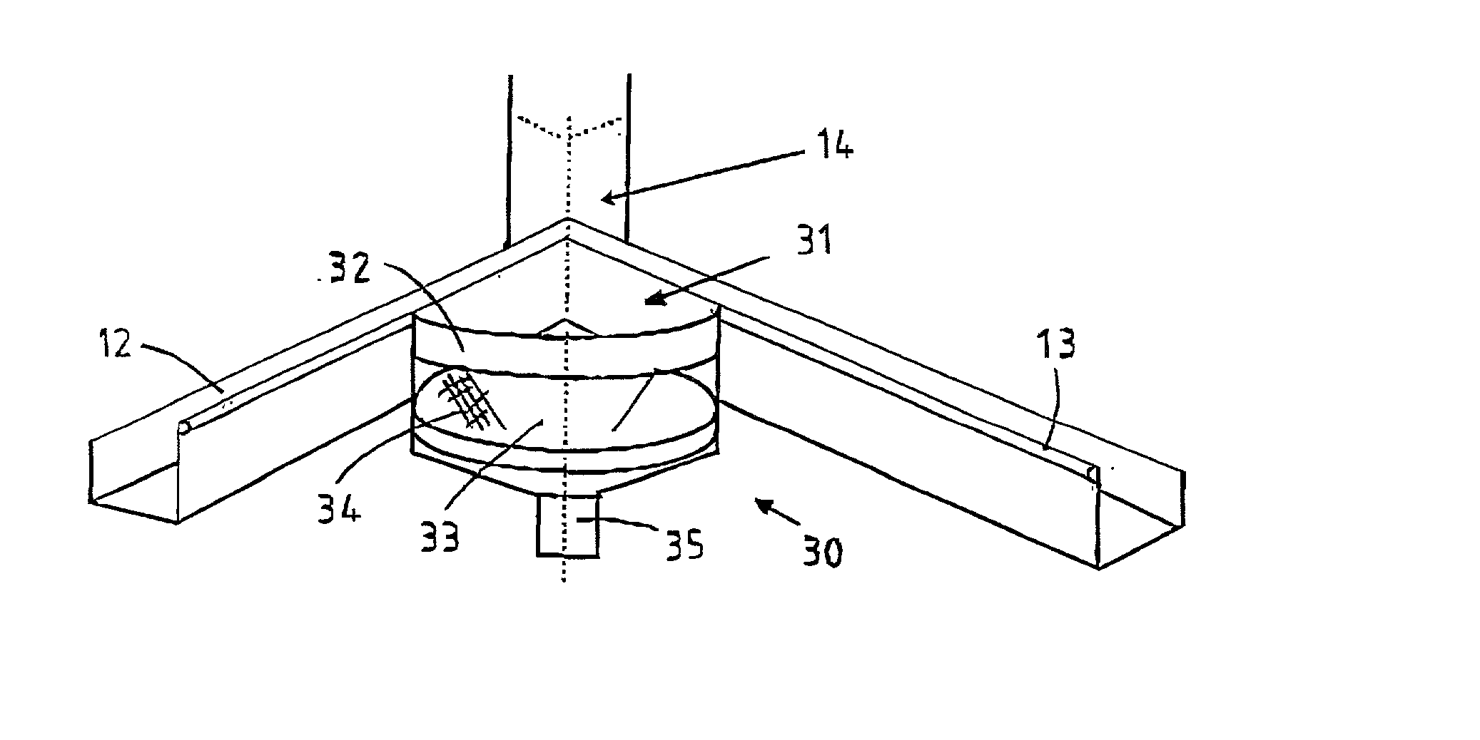
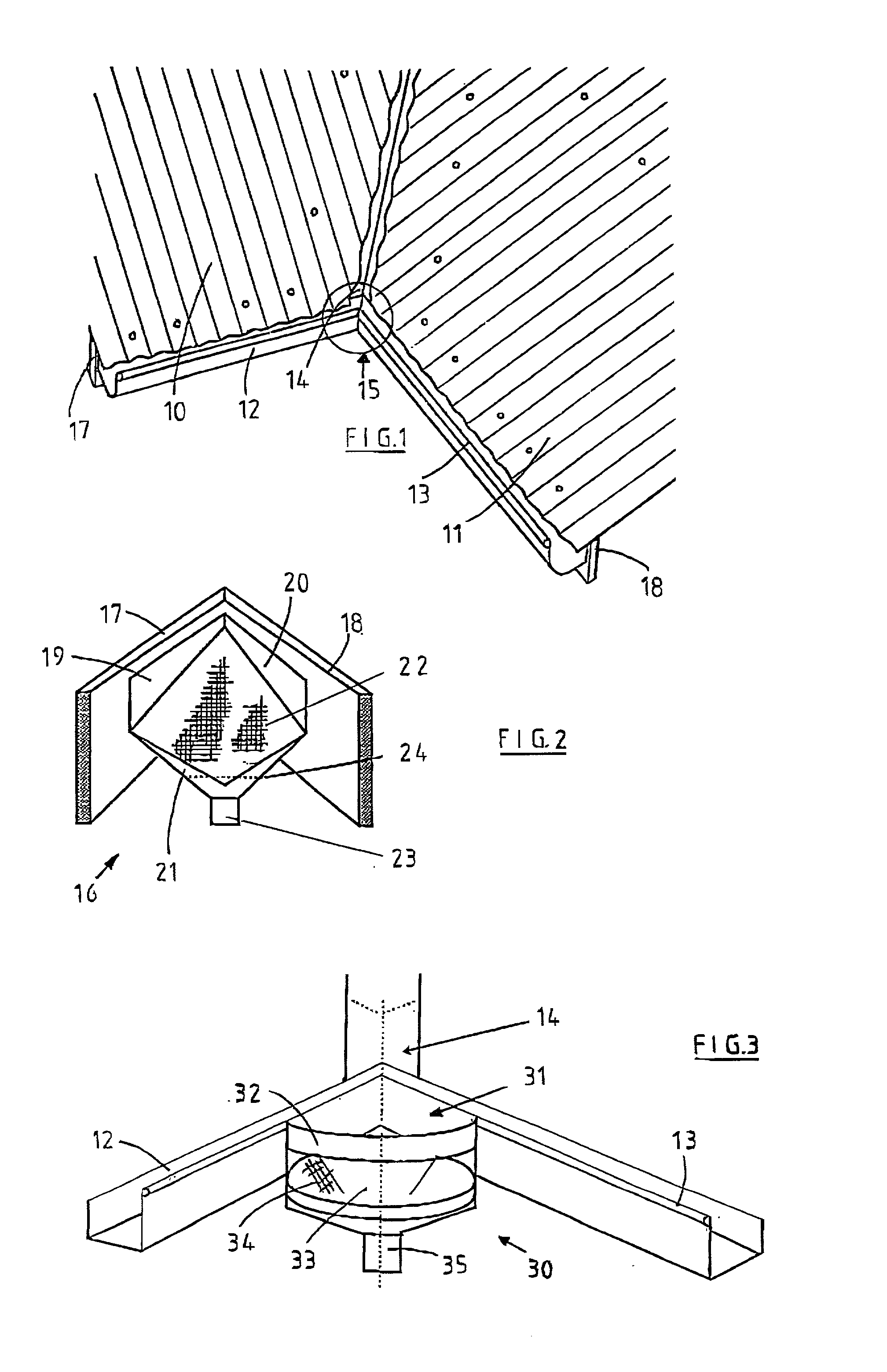
[0011] The compartment can optionally include a secondary screen located between the primary screen and the outlet, to prevent the ingress of vectors such as mosquitoes to the outlet. Such a secondary screen is mandatory to meet government requirements if used in conjunction with the catchment and storage of rain water.

[0012] Preferably, the internal corner rain head will include flanges projecting upwardly from two adjacent sides to enable connection to the fascia or other support means by screws, nails or like fixing arrangements. Such flanges also act as "a splash back" to prevent the fascia from water damage.

[0013] The primary screen is typically angled so that the majority of rainwater and debris hits the screen as it falls through the gutter at between about 45.degree. and 60.degree.. This angle is skewed towards 45.degree. for light rainfalls and towards 60.degree. for high rainfalls by notching the upper edge of the primary screen upwards or downwards while maintaining the b...


PUM


Abstract

A method and apparatus for preventing the blockage of an internal corner roof gutter (31). An opening is formed at the intersection of the two gutters (12, 13) and a rainwater head (30) with attached downpipe is fitted under the opening. The rainwater head can be designed to include an arcuate section (32) which extends between the two faces of the gutter.

Description

[0001] This invention relates to rainwater guttering systems for roofs of buildings, and is particularly concerned with a method and apparatus for preventing the blockage of internal corner roof gutters located at the bottom of valley gutters.[0002] A roof valley is the region where two inclined roofs meet. This region has a substantially V-shaped cross-sectional configuration and generally slopes in one direction toward the edge of the building. A metal tray or gutter is located in the roof valley to collect water flowing from the roof cladding and to direct the water to a roof gutter. During downpours, very large volumes of water and debris can be collected from the roof and wash down into the roof gutter. The design of the roof gutter is such that the flow from the valley gutter is split in half, with one portion going with the flow in the roof gutter and the other portion being pushed against the flow. This can create blockage in the roof gutter if debris is present, and cause a...

Claims


Application Information

Patent Timeline
IPC IPC(8): E04D13/064E04D13/076E04D13/08E04F19/00
CPCE04D13/0767E04D13/08E04D13/0645E04D13/064E04F19/00
Inventor WADE, RODNEY
Owner WADE RODNEY GEORGE
Why Eureka
Try Eureka