Sliding-Jacket Pump

a sliding-jacket pump and pump body technology, applied in the field of pumps, can solve the problems of valves subject to gravity forces, failure to operate, and sealing, and achieve the effects of avoiding slipping, avoiding slipping, and avoiding slipping

Active Publication Date: 2008-10-02
ALBEA LACROST
View PDF16 Cites 0 Cited by
  • Summary
  • Abstract
  • Description
  • Claims
  • Application Information

AI Technical Summary

Benefits of technology

[0009]The object of the present invention is to solve these technical problems satisfactorily.

Problems solved by technology

However, this valve is independent of the other constituent elements of the pump and is made in the form of parts which are attached to the body, which creates problems with regard to sealing, coordination during operation and assembly difficulties.
Furthermore, such a valve is subject to the forces of gravity and may fail to operate in the case when the pump is used in the inclined or inverted position.

Method used


Image

  • Sliding-Jacket Pump
  • Sliding-Jacket Pump
  • Sliding-Jacket Pump

Examples


Embodiment Construction

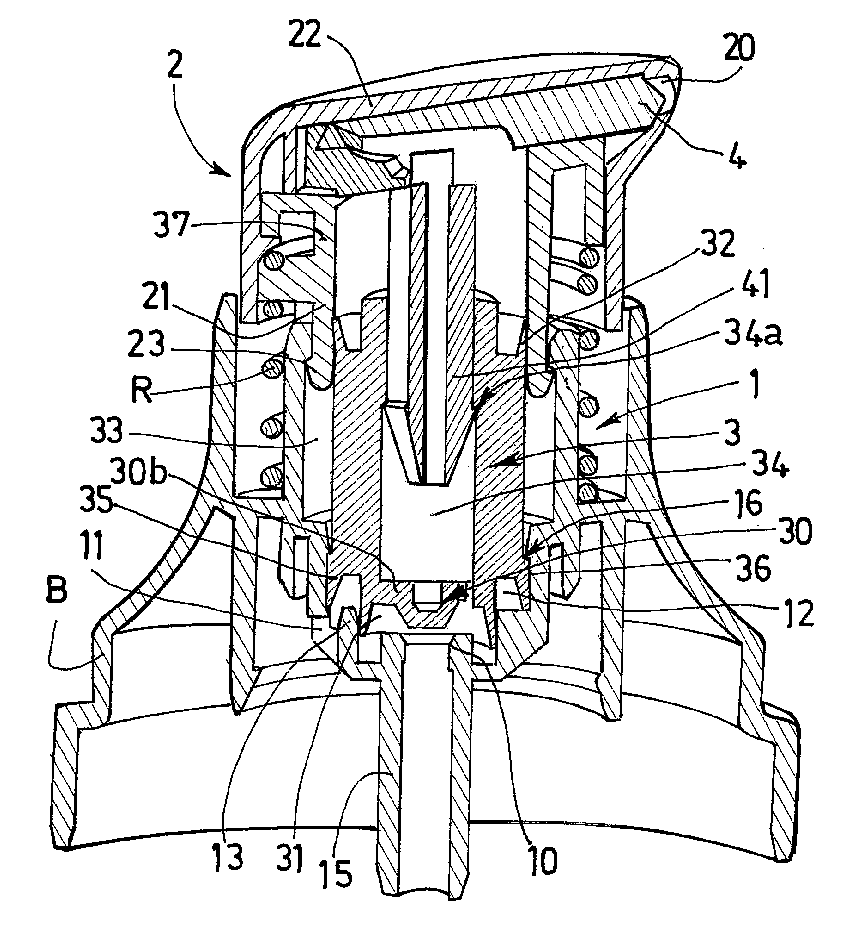
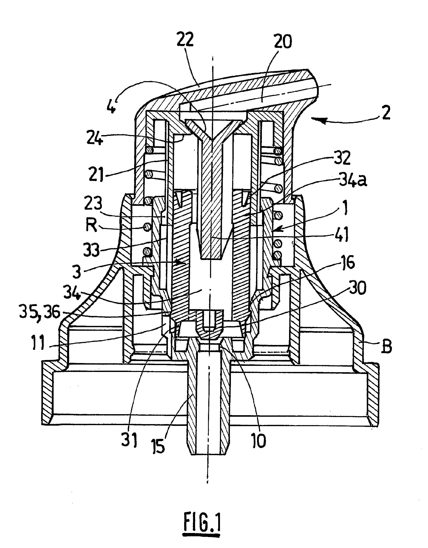
[0033]The pump of the invention comprises, as shown in FIGS. 1 and 2, a generally cylindrical body 1, the wall of which delimits internally a metering chamber.

[0034]In the embodiment of FIG. 1, the body 1 is mounted in a ring B which is designed to be fixed to the neck of a product reservoir which is in the form of a bottle or more generally a cylindrical container (not shown).

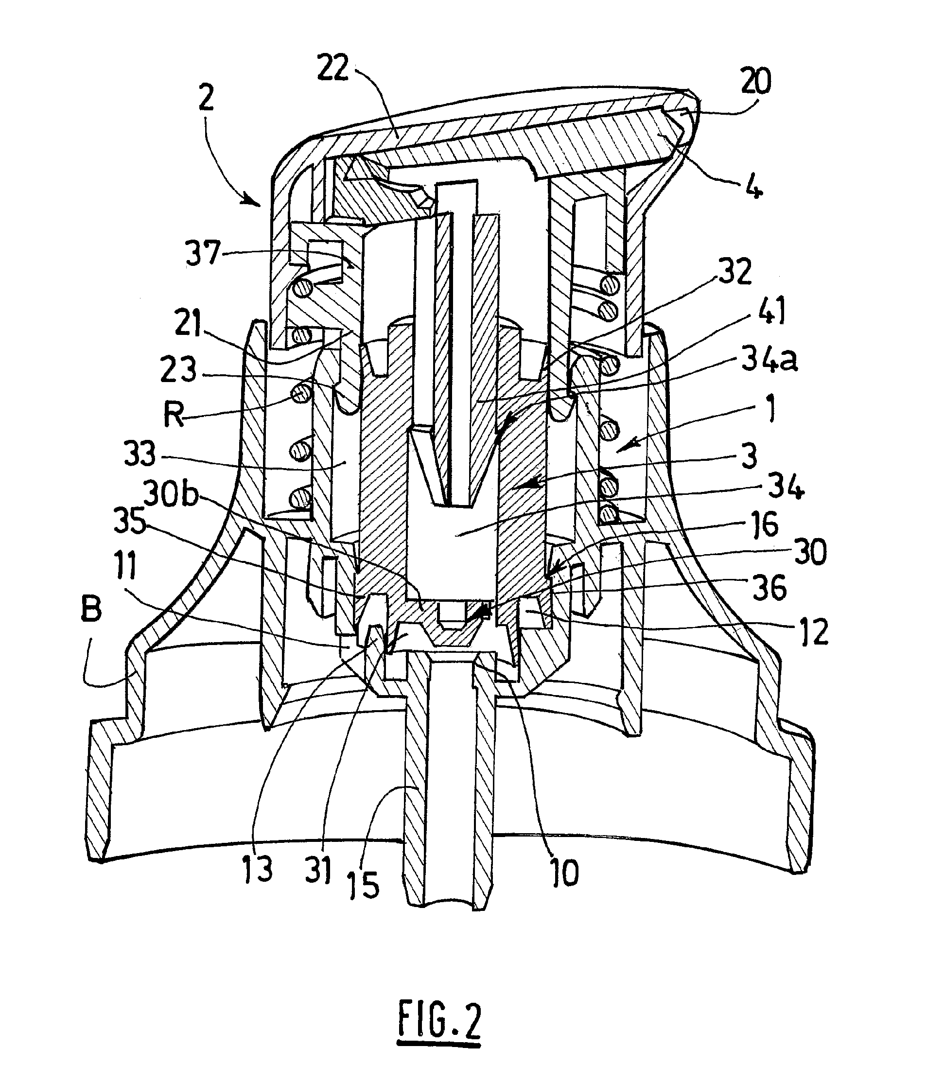
[0035]In the variant of FIG. 2, the ring B is made in a single piece with the body 1.

[0036]The metering chamber of the pump is provided, in the lower part, with an intake orifice 10 which is extended downwards into the reservoir by an intake tube 15. The chamber has, in the upper part, an opening into which there is introduced a sleeve 21 borne by an actuation head 2.

[0037]The head 2 forms an axially displaceable push-button, and the sleeve 21 is covered by a shrunk-fit section or cap 22.

[0038]The lower perimeter of the sleeve 21 is provided with radial retaining protrusions 23 which cooperate with an upper co...


PUM


Abstract

A pump for a liquid cosmetic product dispenser including a body defining a metering chamber provided with an admission orifice at the bottom and having an opening at the top into which is inserted a sleeve carried by an axially movable operating head which is provided with a delivery duct and an open/close element and is acted upon by a return spring mounted on the outside of the body. The body encloses a jacket that moves axially inside the chamber and at least partly inside the sleeve and supports a lower valve for closing the admission orifice.

Description

CROSS-REFERENCE TO RELATED APPLICATIONS[0001]The present application is a continuation of pending International patent application PCT / FR2006 / 002479 filed on Nov. 7, 2006 which designates the United States and claims priority from French patent application 0553876 filed on Dec. 14, 2005, the content of which is incorporated herein by reference.FIELD OF THE INVENTION[0002]The present invention relates to a pump which is intended more particularly for metering and dispensing liquid cosmetic products such as creams or gels.BACKGROUND OF THE INVENTION[0003]The known pumps which are used in this type of application generally comprise a body which delimits a metering chamber provided in the lower part with an intake orifice and having in the upper part an opening into which there is introduced a sleeve borne by an axially displaceable actuation head which is provided with a discharge conduit and with a closure element and which moreover cooperates with a return spring mounted on the exter...

Claims


Application Information

Patent Timeline
Patent Type & Authority Applications(United States)
IPC IPC(8): B65D88/54
CPCB05B11/0016B05B11/3004B05B11/3094B05B11/3074B05B11/3066B05B11/0044B05B11/0067B05B11/0064B05B11/1004B05B11/1066B05B11/1094B05B11/1074
Inventor ROSSIGNOL, ERIC
Owner ALBEA LACROST
Why Eureka
Try Eureka