Wrist-portable equipment

a technology of carrying equipment and carrying cases, which is applied in the field of carrying cases and carrying cases, can solve the problems of certain limitations of this approach

Active Publication Date: 2002-11-14
SEIKO INSTR INC
View PDF6 Cites 29 Cited by
  • Summary
  • Abstract
  • Description
  • Claims
  • Application Information

AI Technical Summary

Problems solved by technology

Thus, there is a certain limitation regarding this approach.

Method used


Image

  • Wrist-portable equipment
  • Wrist-portable equipment
  • Wrist-portable equipment

Examples


Embodiment Construction

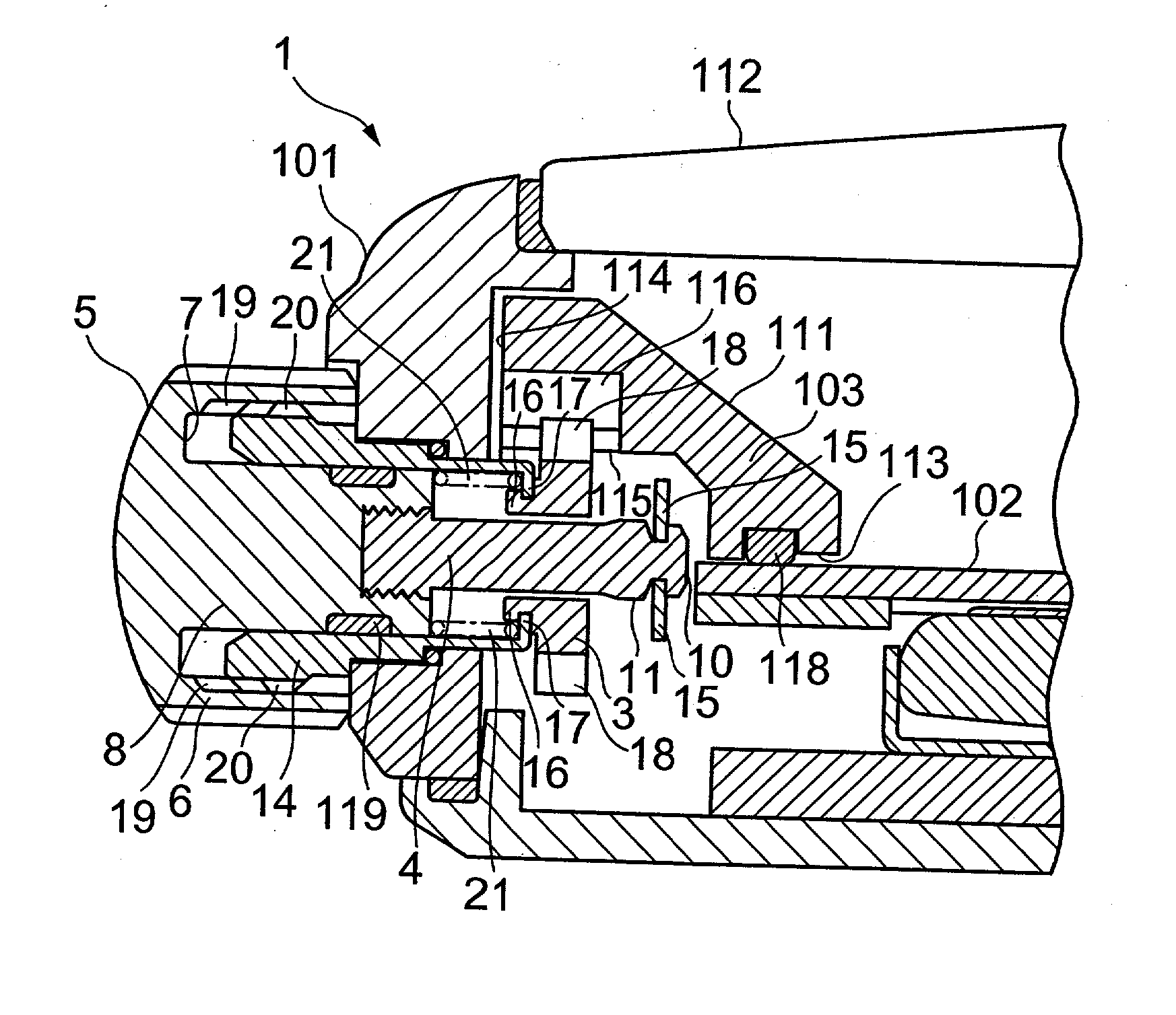
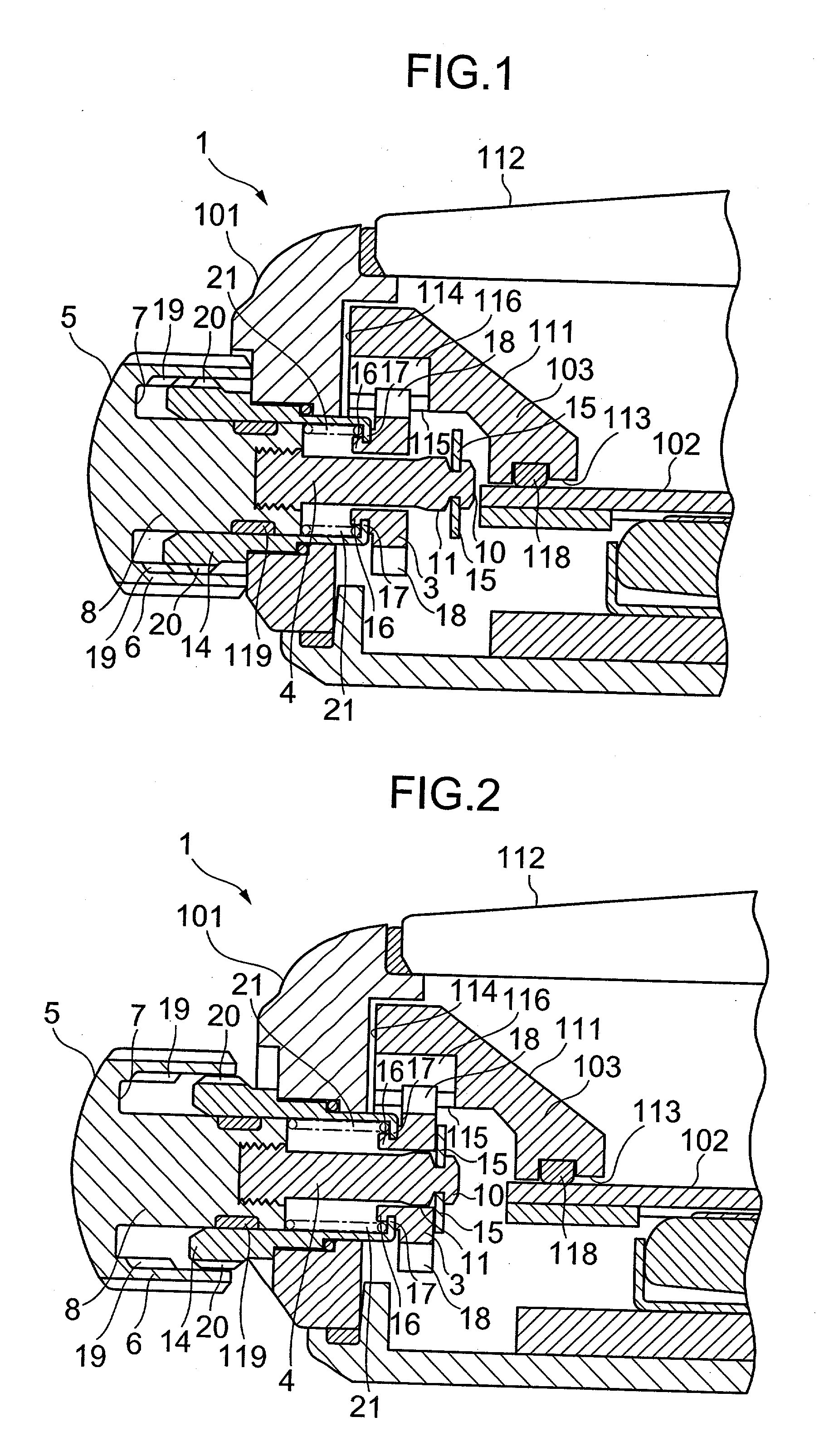
[0053] FIGS. 6 and 7 are side elevation cross-sectional view showing a modification example of a wristwatch 1 in accordance with the mode of the embodiment described in FIGS. 1 to 5. FIG. 6 shows the locked state of the scale ring 103 and FIG. 7 shows the released state thereof, respectively. Note that, in FIGS. 6 and 7, the same reference numerals are used to indicate the same elements as those in the above-described prior art and the mode of embodiment and the explanation therefor will be omitted.

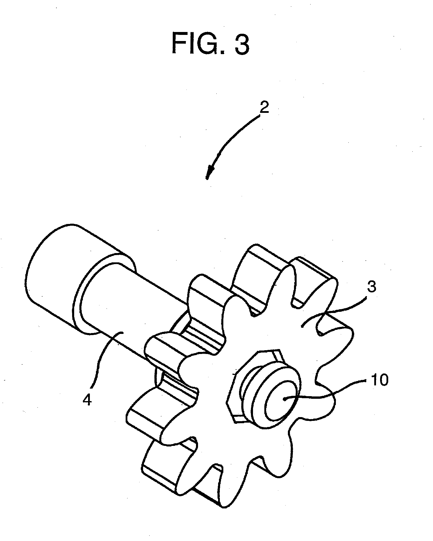
[0054] In FIGS. 6 and 7, the wristwatch 22 has the stem 5 on the side surface of the watch case 101 and has the scale ring 103 in the interior of the watch case 101. This stem 5 is made of metal material and has a cup-shaped outer shell 7. Also, a cylindrical shaft 8 is formed integrally with an inner bottom surface portion of the outer shell 7. Furthermore, a cylindrical operating shaft 23 having a diameter that is substantially half of that of this shaft 8 is formed integrally with the ...


PUM


Abstract

To provide a wrist-portable equipment that may prevent malfunction of an internal rotational ring. There is provided a wrist-portable equipment including: a case, an internal rotational ring to be used as a display member for rotating independently and separately from a gear train of circumferential divisional hour/minute/second within the above-described case, an operating shaft that may be pushed into and drawn out of the above-described case, a clutch for transmitting the rotation of the above-described operating shaft to the above-described internal rotational ring and for releasing the transmission of the rotation by pushing in the above-described operating shaft; and a stem provided at one end portion of the above-described operating shaft and disposed on a side surface portion of the above-described case.

Description

[0001] 1. Field of the Invention[0002] The present invention relates to a wrist-portable equipment, and more particularly to a wrist-portable equipment provided with a display member rotating independently and separately from a gear train of circumferential divisional hour / minute / second.[0003] 2. Description of the Prior Art[0004] In a wrist-portable equipment, a technology for rotating and operating a display member provided in an interior of a case member by a stem provided in the outside of the case member is currently known. FIG. 8 is a plan view showing a body of a conventional wristwatch 100. FIG. 9 is a side elevational cross-sectional view showing a primary part of the wristwatch 100 described in FIG. 9. In FIGS. 8 and 9, the wristwatch 100 has a letter plate 102 and a scale ring 103 within a watch case 101.[0005] Also, a stem 104 for rotating the scale ring 103 is mounted independently and separately from a stem 105 for correcting hour / minute / second hands, on the side surfa...

Claims


Application Information

Patent Timeline
Patent Type & Authority Applications(United States)
IPC IPC(8): G04B19/28G04B27/00G04B27/04G04B37/06
CPCG04B37/06G04B27/04
Inventor OOMORI, NOBUKAZUHIRANUMA, HARUKI
Owner SEIKO INSTR INC
Why Eureka
Try Eureka