

Molded case circuit breaker
- Summary
- Abstract
- Description
- Claims
- Application Information
AI Technical Summary
Benefits of technology
Problems solved by technology
Method used
Image

Examples
Embodiment Construction
[0025] Hereunder, an embodiment of the present invention will be described with reference to the accompanied drawings. In the figures, the same parts as those in FIGS. 6(a) and 6(b) are denoted by the same reference numerals, and the description is omitted.
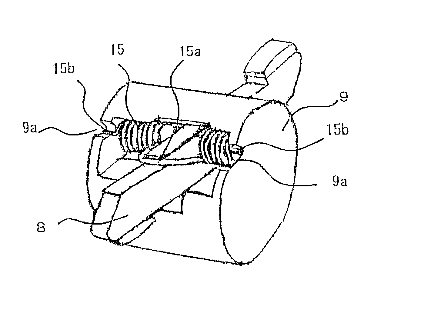
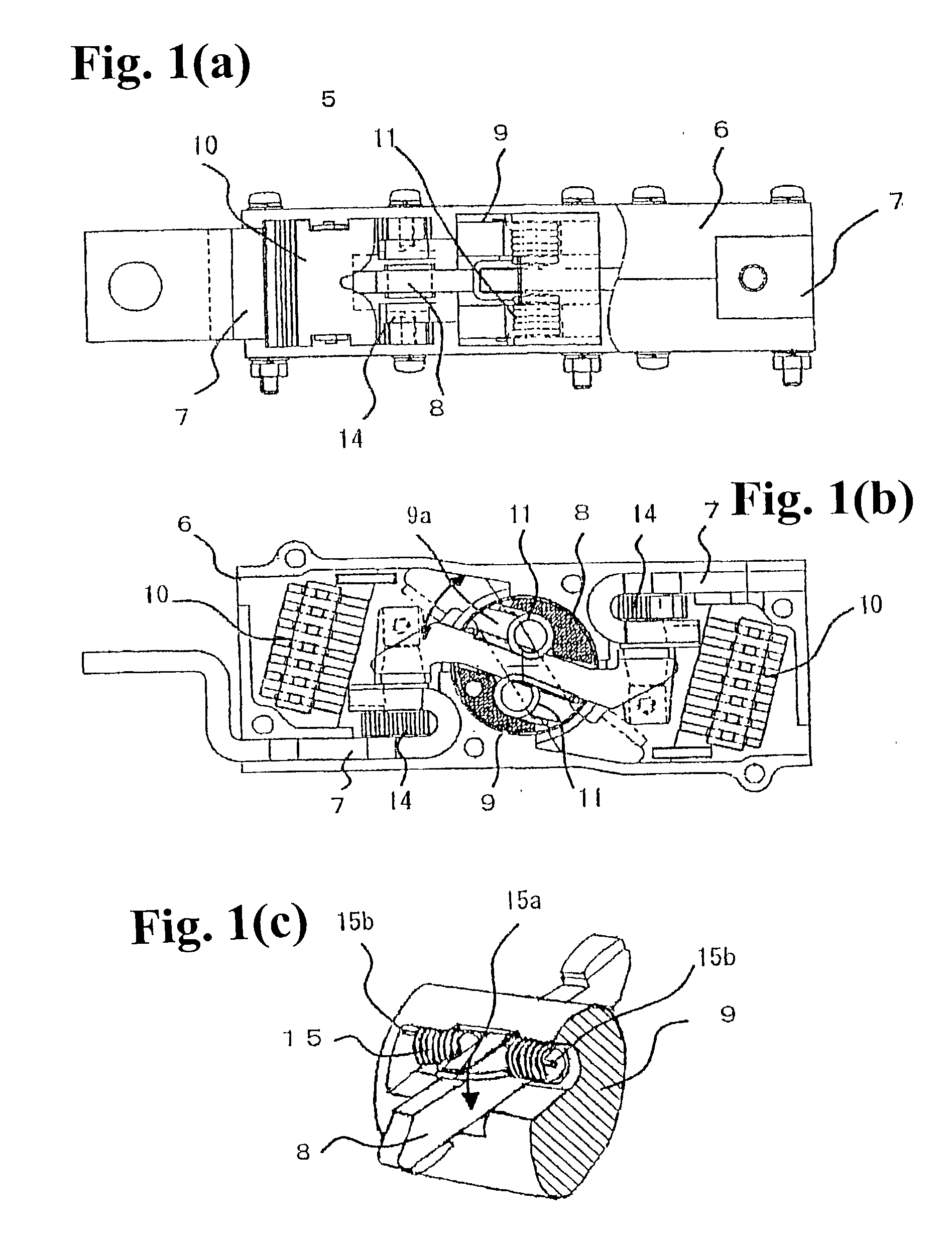
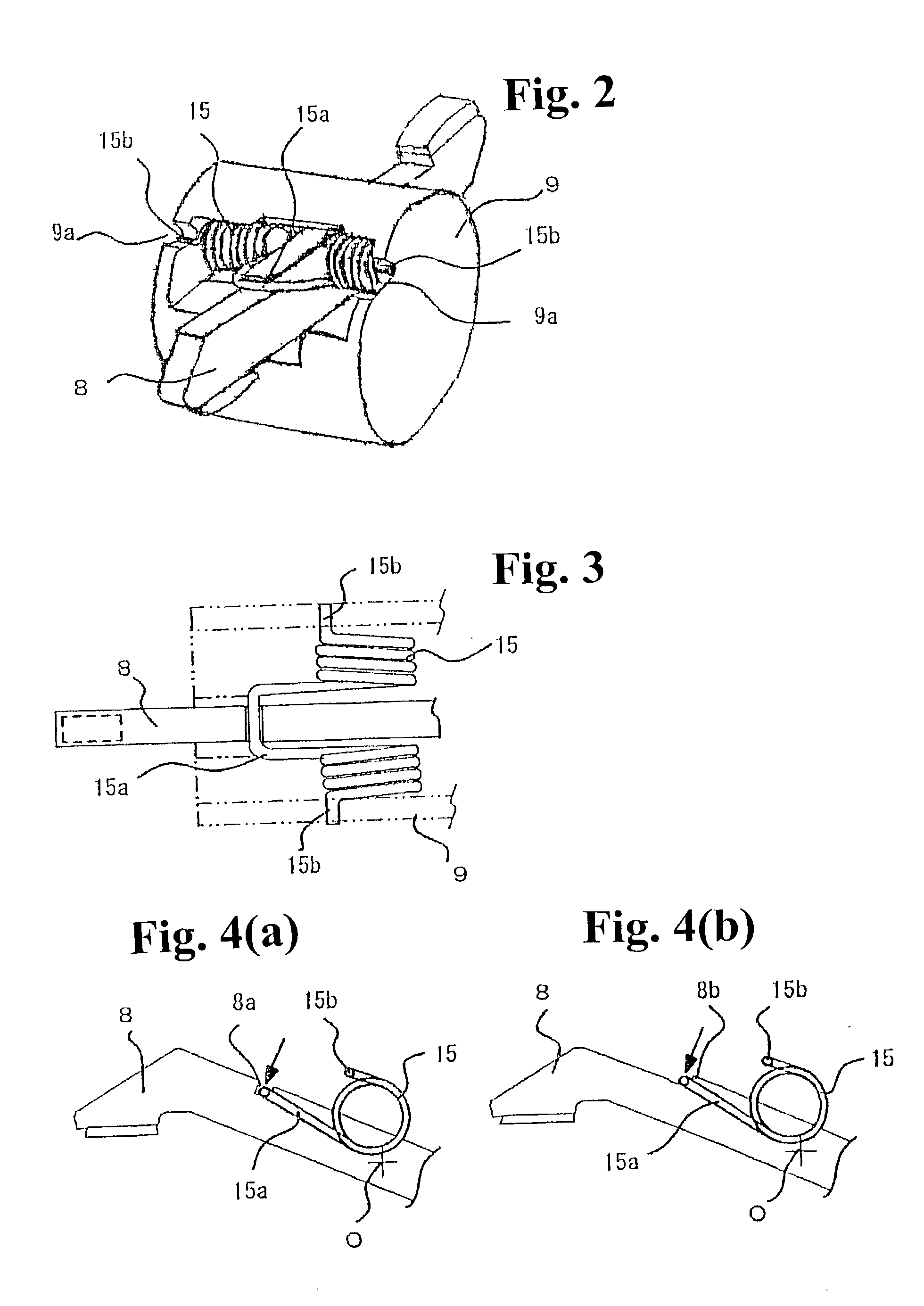
[0026] First, in FIGS. 1(a) to 1(c), a current-interrupting section 5 of a molded case circuit breaker essentially has a configuration similar to that shown in FIGS. 6(a) and 6(b), but a support structure for a movable (rotary) contact shoe 8 held in a contact shoe holder 9 is different. As shown in FIG. 1(c), as the pressure springs 11, torsion coil springs 15 with offset arms 15a are disposed above and under the movable contact shoe 8 so as to press and hold the movable contact shoe 8 in a predetermined position.
[0027] The torsion coil spring 15 has the offset arm portion 15a formed in the center of the coil. The offset arm portion 15a has a U-shape and drawn out from the coil laterally, as shown in FIG. 3. Legs 15b are provided...
PUM
 Abstract
Description
Claims
Application Information