Phase-coupled clock signal generator and character generator comprising such a phase-coupled clock signal generator.

a phase-coupled clock signal and generator technology, which is applied in the direction of instruments, television systems, pulse techniques, etc., can solve the problems of increasing the costprice affecting the efficiency of the clock signal generator, and difficulty in realising the frequency-determining components of the start-stop oscillator in the integrated circuit (ic) within the required tolerance limits, so as to achieve cost saving

Inactive Publication Date: 2002-12-26
ENTROPIC COMM INC
View PDF8 Cites 3 Cited by
  • Summary
  • Abstract
  • Description
  • Claims
  • Application Information

AI Technical Summary

Benefits of technology

[0008] A favourable embodiment of the clock signal generator, in which the control signal is periodical, is characterized in that the control means for generating the counting value comprise a counting circuit for counting clock pulses in the clock signal during the period when the first value of the control signal is available. Such an embodiment has the advantage that a defined periodical time interval required for generating the counting value is used without any additional provisions.
[0009] A further favourable embodiment of the clock signal generator according to the invention is characterized in that the control means are realised to adapt the adjusting value, if the difference between the counting value and the reference value is larger than a predetermined value. This results in the effect that the frequency, if gradually changing due to, for example, temperature effects, is not adapted until it has varied by more than a predetermined value. This will be very much appreciated when using the clock signal generator in a character generator in which a slow variation of the frequency, and hence of the character width, is acceptable. A steady and stable picture is obtained with said embodiment by correcting the frequency only after it has reached predetermined limits.
[0010] A further embodiment of the clock signal generator according to the invention is characterized in that the input of the start-stop oscillator for receiving the control signal is coupled to delay means for delaying the transition from the first to the second value of the control signal. This provides the effect that the oscillator reaches its non-oscillating state only with a predetermined delay upon the transition to the second value of the control signal. This is particularly sensible in applications of the clock signal generator in which the periodical discontinuity in the clock signal is acceptable, but must remain limited in time. For example, a character generator is enabled to perform tasks also during the line flyback period.
[0011] As previously stated, a clock signal generator according to the invention is eminently suitable for integration with, for example a character generator. Such a character generator comprises, inter alia, a horizontal position counter to which the clock signal is applied for positioning the characters in a picture line. An embodiment of the character generator according to the invention is characterized in that the horizontal position counter is constituted by the counting circuit of the clock signal generator. This limits the number of digital components and thus leads to a further saving of costs.

Problems solved by technology

In practice it has been found difficult to realise the frequency-determining components of a start-stop oscillator in an integrated circuit (IC) within the required tolerance limits.
However, such components as well as the required connection pins on an IC raise the costprice of the clock signal generator.
Moreover, adjusting the components is a time-consuming and costly activity.
This results in the effect that the frequency, if gradually changing due to, for example, temperature effects, is not adapted until it has varied by more than a predetermined value.
This limits the number of digital components and thus leads to a further saving of costs.

Method used


Image

  • Phase-coupled clock signal generator and character generator comprising such a phase-coupled clock signal generator.
  • Phase-coupled clock signal generator and character generator comprising such a phase-coupled clock signal generator.
  • Phase-coupled clock signal generator and character generator comprising such a phase-coupled clock signal generator.

Examples


Embodiment Construction

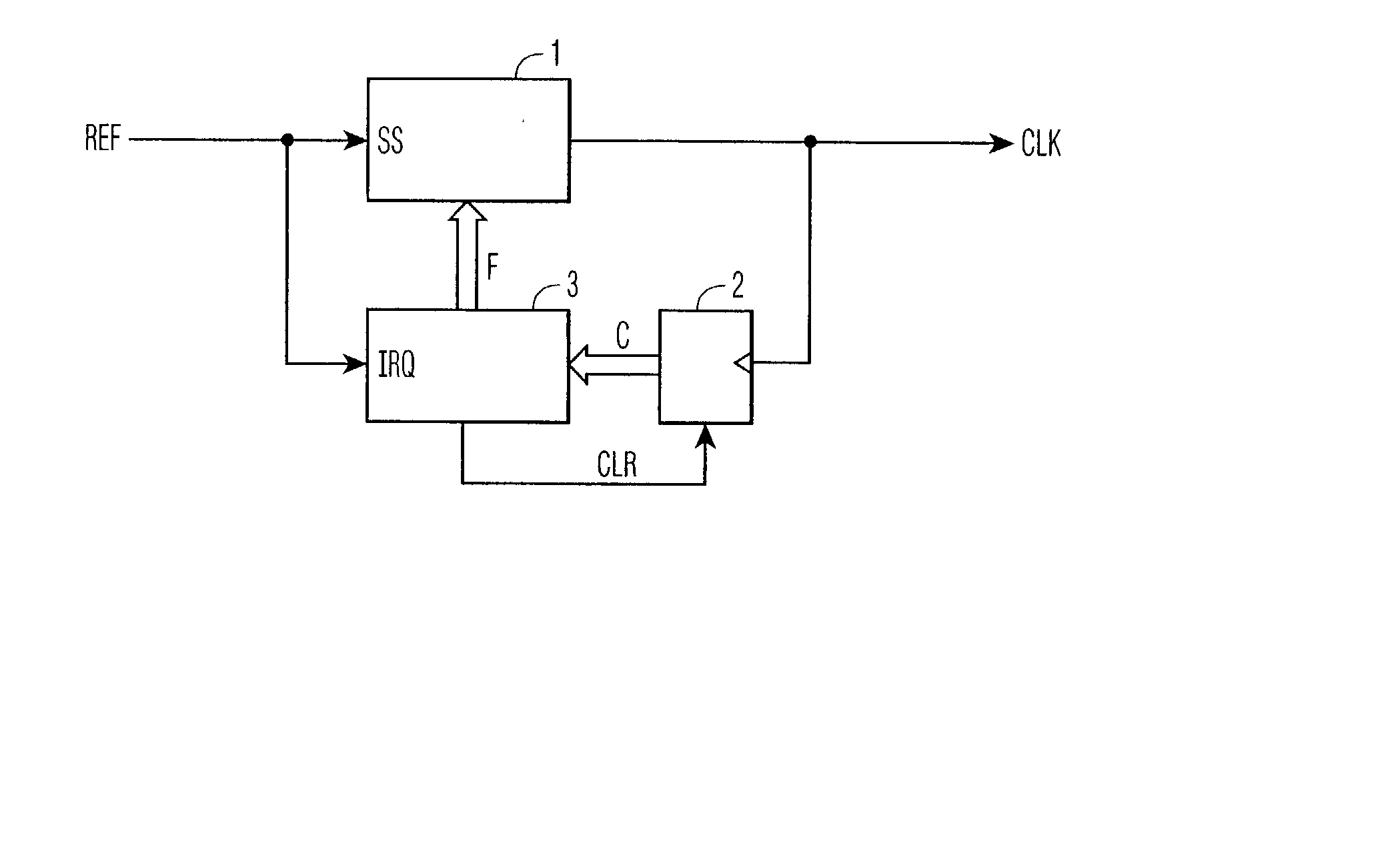
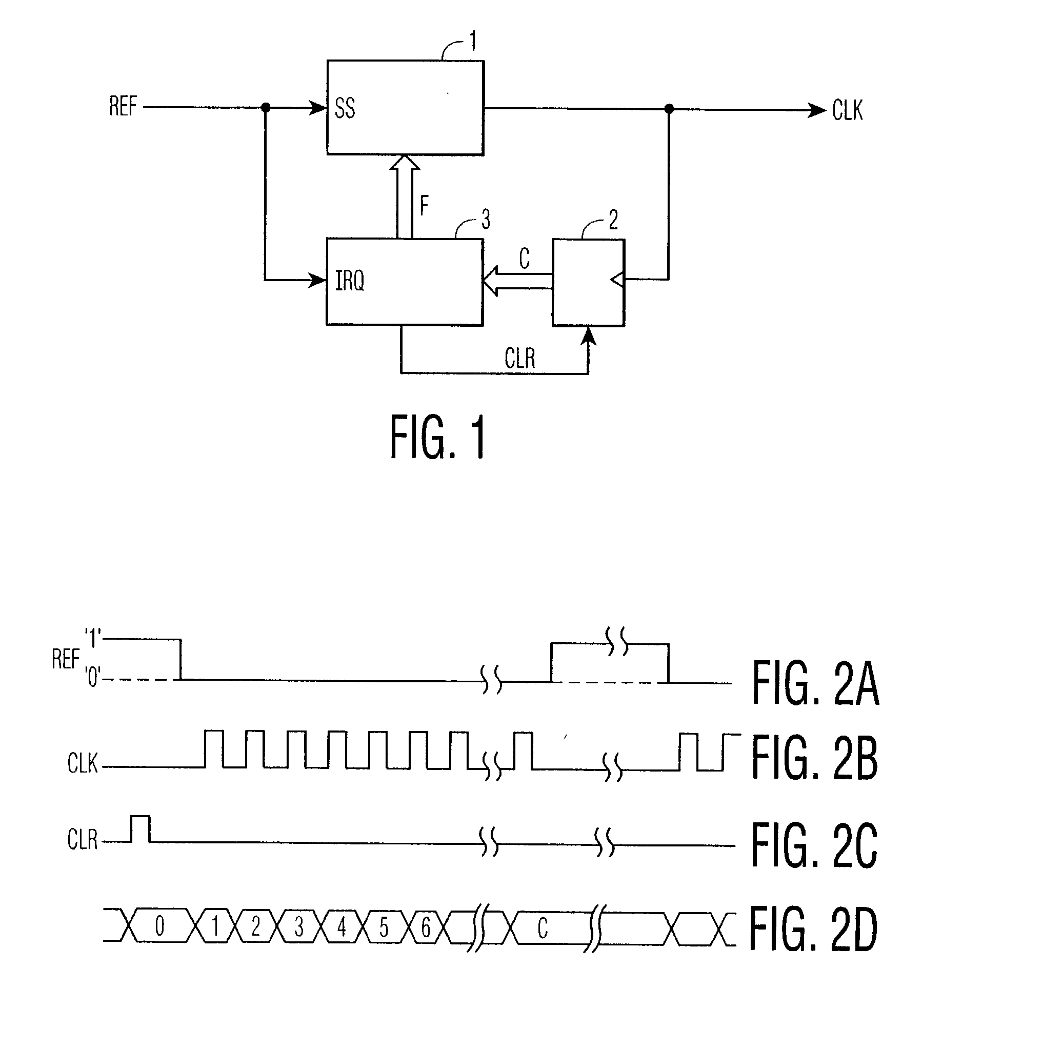
[0024] FIG. 1 shows diagrammatically the structure of a phase-coupled clock signal generator according to the invention. The clock signal generator comprises a start-stop oscillator 1 having a first input SS to which a periodical control signal REF is applied and a further input to which an adjusting value F is applied. The start-stop oscillator 1 supplies an output signal CLK which will be further referred to as clock signal. This clock signal is applied to a counter 2. The counter 2 generates a counting value C and applies it to a control circuit 3. The control circuit 3 is adapted to generate the adjusting value F in response to the received counting value C and a reference value R stored in the control circuit. The control circuit 3 further receives the control signal REF at an input IRQ and applies a reset signal CLR to the counter 2. In practice, the control circuit 3 may comprise a microprocessor, for example the type 84C640 of Philips. The input IRQ is then preferably a so-c...


PUM


Abstract

A phase-coupled clock signal generator comprises a startstop oscillator (1) to which a control signal is applied. The clock frequency is dependent on an adjusting value (F). For adjusting and monitoring the clock frequency, the clock signal generator is provided with a counter (2). This counter counts the number of received clock pulses during a predetermined period and generates a corresponding counting value (C). A control circuit (3) compares the counting value (C) with a reference value and adapts the adjusting value (F). Such a clock signal generator is suitable for On Screen Display applications in a television receiver.

Description

[0001] The invention relates to a phase-coupled clock signal generator comprising a start-stop oscillator having an input for receiving a control signal to allow oscillation in response to a first value of the control signal and no oscillation in response to a second value of the control signal. The invention also relates to a character generator for generating characters on a display screen, which generator comprises such a clock signal generator.DESCRIPTION OF THE PRIOR ART[0002] A Phase Locked Loop (PLL) is often used for generating a clock signal. Such a PLL generates a continuous clock signal which is coupled in phase and frequency to an applied periodical reference signal. Phase coupling of a clock signal to a reference signal, which will further be referred to as control signal, is also achieved by means of a start-stop oscillator. Such a start-stop oscillator is described in British Patent Specification GB 1,276,025. The start-stop oscillator oscillates at a predetermined fr...

Claims


Application Information

Patent Timeline
Patent Type & Authority Applications(United States)
IPC IPC(8): G09G5/12G09G5/18G09G5/22H03K3/0231H03K4/502H03L7/181H04N5/278
CPCH03K3/0231H04N5/278H03L7/181H03K4/502G09G5/18
Inventor DEN OUDEN, JOSEPHUS A.A.
Owner ENTROPIC COMM INC
Why Eureka
Try Eureka