Precision laser cutting guide

a laser cutting guide and laser cutting technology, applied in metal sawing devices, metal sawing accessories, manufacturing tools, etc., can solve the problem that the device is not intended for use on hand-held rotary saws, and achieve the effect of precise cutting

Inactive Publication Date: 2003-01-16
HAYDEN JAMES ALAN
View PDF0 Cites 48 Cited by
  • Summary
  • Abstract
  • Description
  • Claims
  • Application Information

AI Technical Summary

Benefits of technology

0010] The primary objective of this invention is to provide a more precise cutting guide with micro-adjustment means which attaches to a fixed member of a stationary saw, as opposed to a moveable portion of the stationary saw. This device is not intended for use on hand-held rotary saws. In furtherance of this objective, the device includes a vertical frame member having a base clamp which attaches to the adjustable floor or the stationary base portion of a miter or chop saw. A proximal end of a horizontal frame member extends from the vertical frame member, wherein a locking ball joint attaches a mounting plate, pivotally attached to a laser guide by a locking pivot pin, to a distal end of th

Problems solved by technology

This device is not intended fo

Method used


Image

  • Precision laser cutting guide
  • Precision laser cutting guide
  • Precision laser cutting guide

Examples


Embodiment Construction

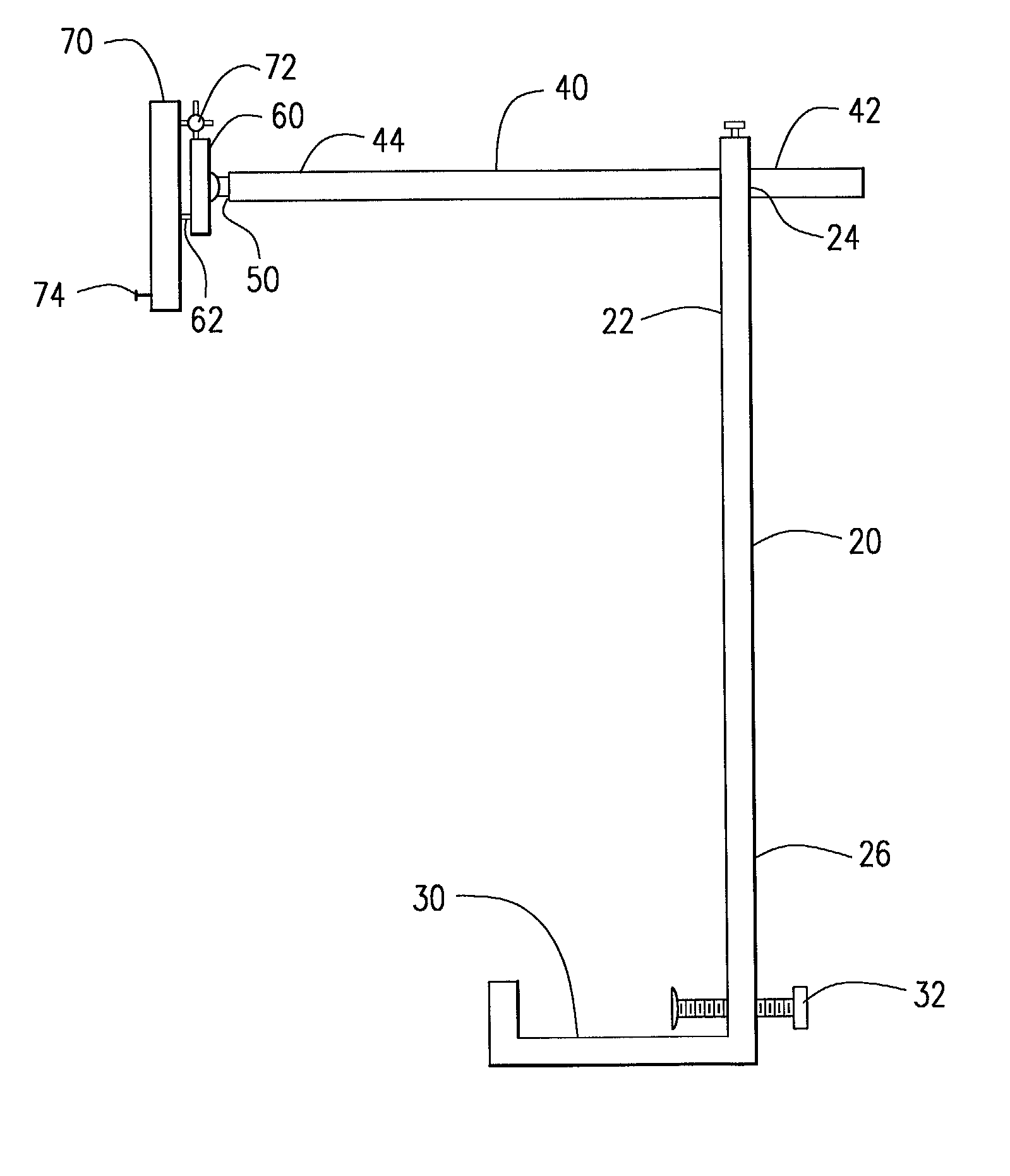
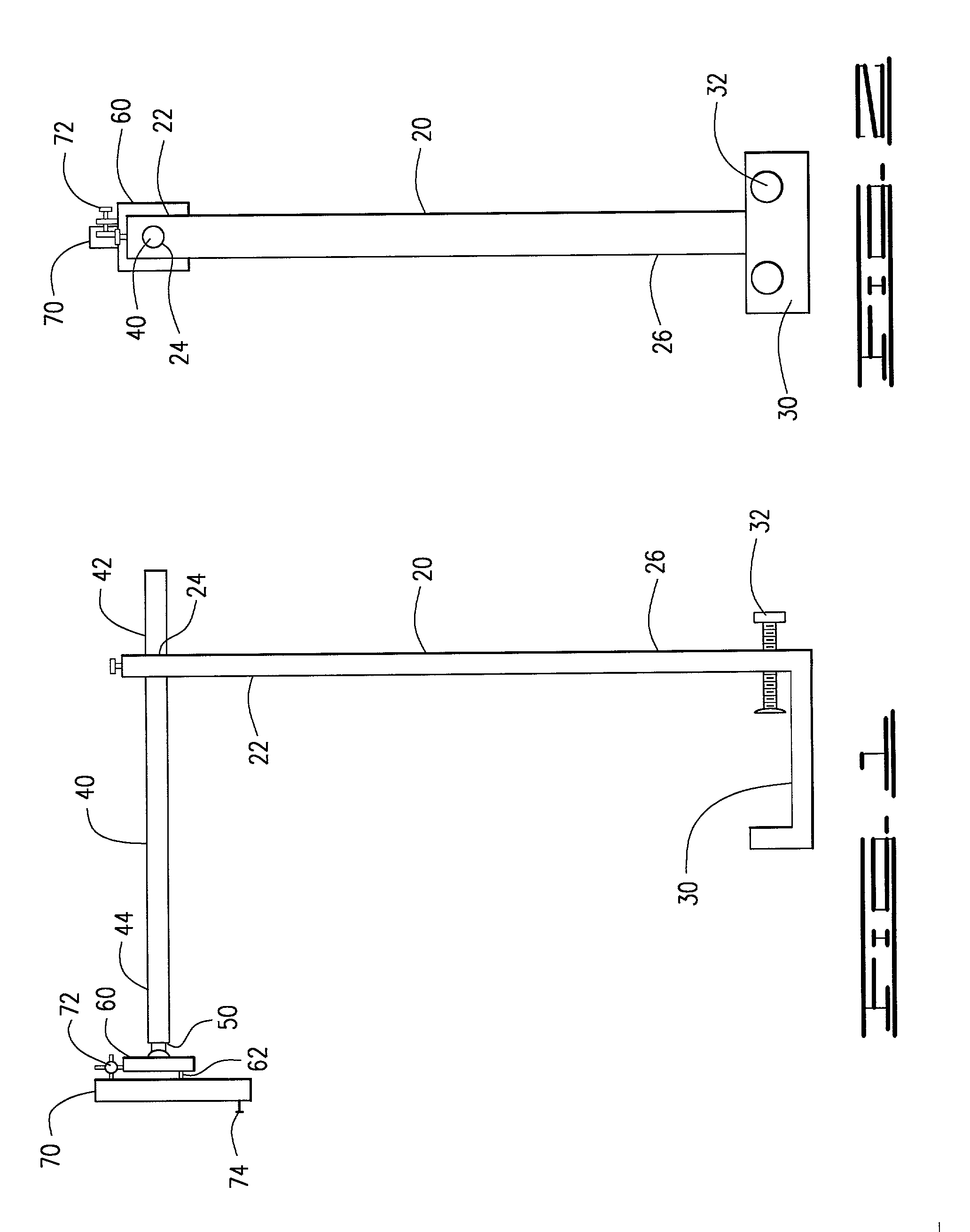
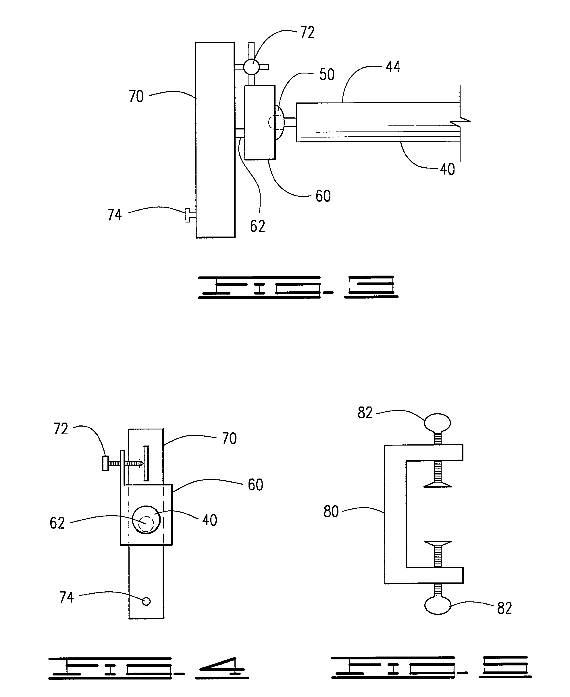
[0017] The invention, as shown in FIGS. 1-5 of the drawings, is a precision laser cutting guide to be attached to a stationary power saw, removably connected to a base portion of the power saw, as opposed to a retractable saw blade portion of the power saw, illuminating a location on the material to be cut with a confined and direct beam of light, the device 10 essentially comprising a vertical frame member 20 having a base clamp 30, a horizontal frame member 40 perpendicularly connected to the vertical frame member 20, a mounting plate 60 connecting to the horizontal frame member 40 by a locking ball joint 50, and a laser guide 70 pivotally attached to the mounting plate 60 having a micro-adjustment means 72 for precision setting of the laser guide 70 at a fixed and precise point on the material to be cut by the power saw indicative of the strike point of the saw blade.

[0018] The vertical frame member 20, as shown in FIGS. 1-2, has an upper end 22 and a lower end 26, the lower end ...


PUM

PropertyMeasurementUnit
Angleaaaaaaaaaa
Lengthaaaaaaaaaa
Widthaaaaaaaaaa

Abstract

The invention is an attachment for a stationary power saw, attaching to an operationally non-moving base or frame member of the power saw, as opposed to the retractable saw blade portion of the power saw, providing a fully adjustable laser cutting guide for designating the strike point of the rotating saw blade on the material being cut by the saw blade.

Description

[0001] Provisional Patent Application, Atty. Doc. No. 2001--Hayden, James A., filed on May 30, 2001. (No Serial No. as of the date of the filing of this Non-provisional Utility Patent Application).I. BACKGROUND OF INVENTION[0002] 1. Field of the Invention[0003] The invention is an attachment for a stationary power saw, attaching to an operationally non-moving base or frame member of the power saw, as opposed to the retractable saw blade portion of the power saw, providing a fully adjustable laser cutting guide for designating the strike point of the rotating saw blade on the material being cut by the saw blade.[0004] 2. Description of Prior Art[0005] The following United States patents are identified and disclosed herein. Several devices are disclosed relating to lighted cutting guides. Those patents are distinguishable from the current invention, in accordance with 35 U.S.C. .sctn..sctn.102 and 103. In U.S. Pat. No. 5,996,460 to Waite, a kerf indicator for a power saw, shown primar...

Claims


Application Information

Patent Timeline
IPC IPC(8): B23D59/00B23Q17/24B27B31/06
CPCB23D59/003B23Q17/24B27B31/06Y10T83/839Y10T83/856Y10T83/828
Inventor HAYDEN, JAMES ALAN
Owner HAYDEN JAMES ALAN
Why Eureka
Try Eureka