Exhaust gas heat exchanger

a heat exchanger and exhaust gas technology, applied in the direction of soldering apparatus, manufacturing tools, light and heating equipment, etc., can solve the problem of insufficient brazing material between the tube and the inner fin

Inactive Publication Date: 2003-01-16
DENSO CORP
View PDF8 Cites 68 Cited by
  • Summary
  • Abstract
  • Description
  • Claims
  • Application Information

AI Technical Summary

Problems solved by technology

Thus, in the event that the aforesaid production method is used, in which the inner fins are inserted into the tubes, the applied brazing material is stripped off when the inner fin is inserted, leading to a possibility that sufficient brazing material cannot be provided between the tube and the inner fin.
Then, when a failure in brazing occurs between the core plate and the tube 1 there occurs a risk that there is caused a leakage between an exhaust gas passage and a coolant passage which are partitioned by the core plate.

Method used


Image

  • Exhaust gas heat exchanger
  • Exhaust gas heat exchanger
  • Exhaust gas heat exchanger

Examples


first embodiment

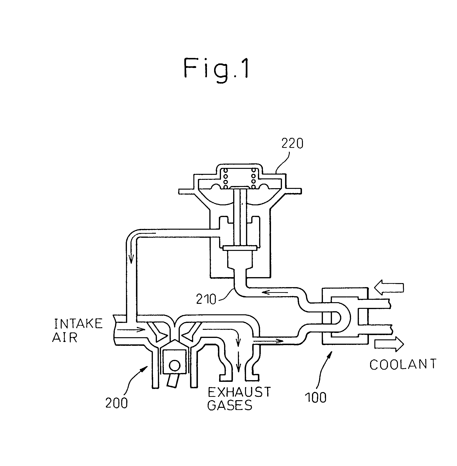
[0029] Firstly, the invention will be described. Hereinafter, embodiments of the invention will be described as an exhaust gas heat exchanging device according to the invention being applied to an EGR-gas cooling system for a diesel engine (an internal combustion engine). FIG. 1 is a view showing the type of an EGR (exhaust gas recirculation) system adopting an exhaust gas heat exchanger (hereinafter referred to as an "EGR-gas heat exchanger") 100 according to the invention. In FIG. 1, reference numeral 200 denotes a diesel engine, and reference numeral 210 denotes an exhaust gas recirculation pipe through which part of exhaust gases discharged from the engine 200 is passed to an intake side of the engine.

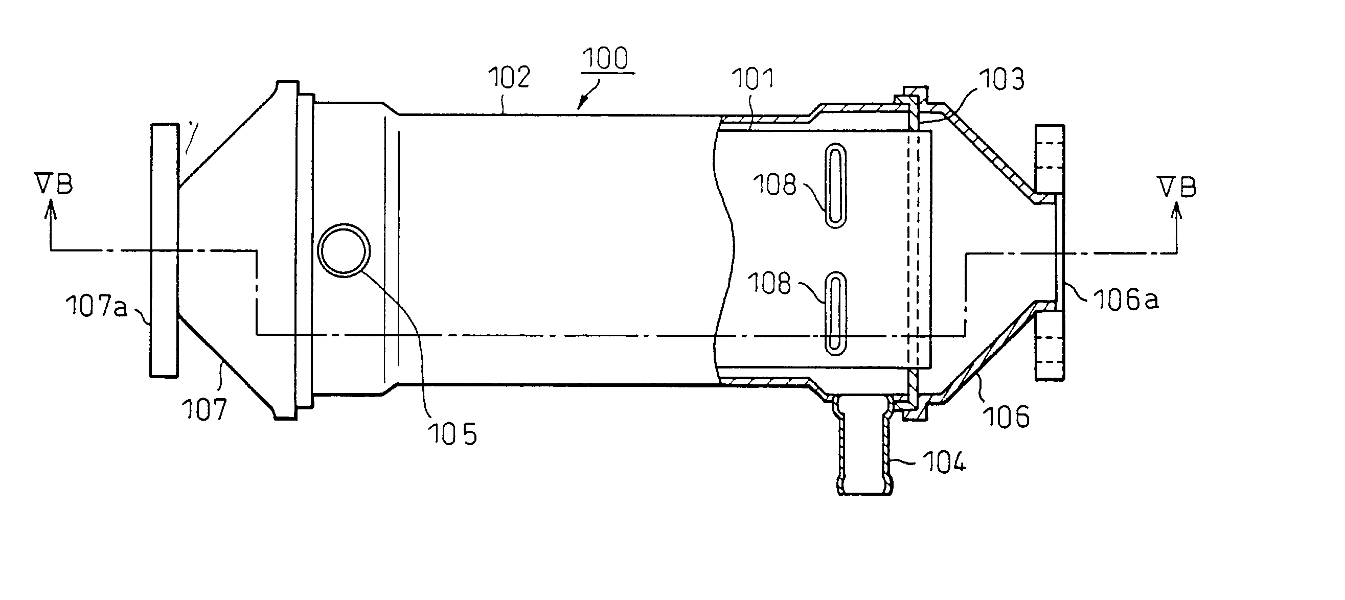
[0030] Reference numeral 220 denotes a known EGR valve disposed at an intermediate position along the length of the exhaust gas recirculation pipe 210 for regulating the volume of EGR gases according to the operating conditions of the engine 200. The EGR-gas heat exchanger 100 is d...

second embodiment

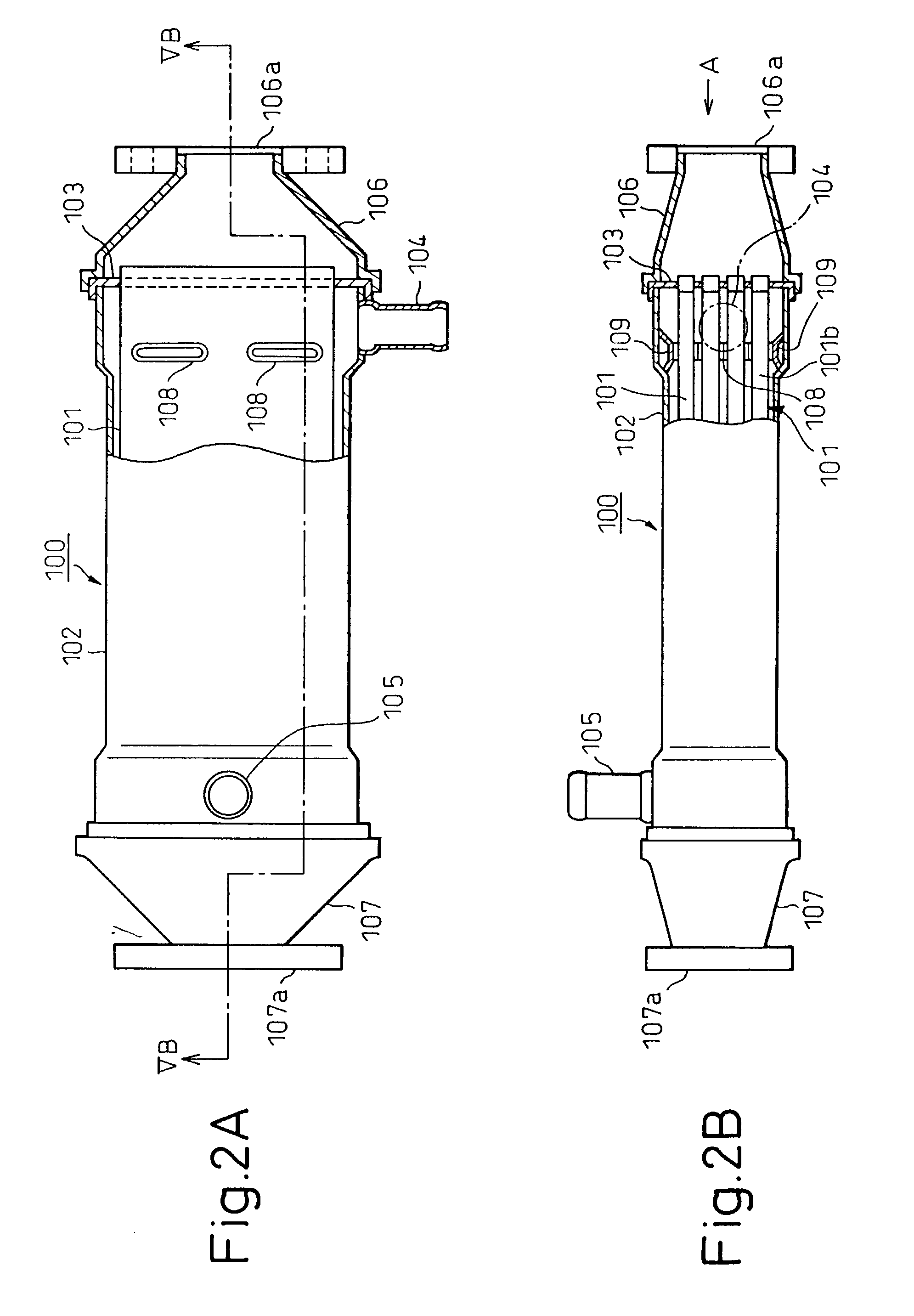
[0055] In addition, as the tube 201 has an asymmetrical configuration as viewed vertically, an assembling error can be prevented that would otherwise occur when the tube is passed through core plates 103 when it is assembled to a tank.

[0056] Next, a third embodiment will be described. While in the aforesaid embodiment the differences in level are formed on the plate which is adapted to be fittingly positioned inside and the joint potions of the plate adapted to be fittingly positioned outside are located on the differences in level, respectively, even if ends of the joint portions of the plate which is fittingly positioned outside are collapsed to be clamped to wrap up the differences in level formed on the plate which is fittingly positioned inside, so that the ends of the joint portions are configured to follow the outer wall surface of the tube, advantages similar to those provided by the first and second embodiments can be obtained. Note that like reference numerals are used to...

fourth embodiment

[0059] FIG. 7 is a view showing a transverse cross section of a tube 401 according to the invention, and the tube 401 is formed by causing two plates 411 each having an identical configuration to fit with each other in such a manner as to face each other. Ends of the plate 411 are bent so that they constitute fitting portions when the plates 411 are fitted with each other. The bent portion 411a of the plate 411 is made longer the other bent portion 411b thereof and a difference in level 411c is formed on the end 411a which is substantially equal in height to the thickness of the plate 411 and which protrudes inwardly of the tube 401.

[0060] The end 411a of the plate 411 is fitted in the other end 411b of the other plate 411 to thereby form the tube 401. As this occurs, a state is created in which the end 411b is fitted in the difference in level 411c, whereby the outer wall surface of the tube 401 is made substantially level thereover. Owing to this, good brazing properties can be pr...


PUM

PropertyMeasurementUnit
thicknessaaaaaaaaaa
bendingaaaaaaaaaa
heat exchange capacityaaaaaaaaaa

Abstract

A tube 101 is constituted by a pair of plates 111a, 111b which are fitted with each other in such a manner as to put an inner fin 101b between the plate 111a and the plate 111b. Differences in level 111c are formed on the second plate 111b, which fits inside, which differences in level each protrude inwardly by a distance equal to the thickness of the first plate 111a, whereby the outer wall surface of the tube 101 is made substantially level thereover. A gap which is formed between the outer wall surface of the tube 101 and a core plate, when the tube is passed through the core plate, can be as small as possible whereby the brazing properties can be improved.

Description

[0001] 1. Field of the Invention[0002] The present invention relates to an exhaust gas heat exchanger, for performing heat exchange between exhaust gases produced when fuel is burnt in an engine and a cooling fluid such as water and, more particularly, to an exhaust gas heat exchanger for cooling exhaust gases for an EGR (exhaust gas recirculation) system (hereinafter referred to as an "EGR-gas heat exchanger").[0003] 2. Description of the Related Art[0004] As a conventional EGR-gas heat exchanger, an EGR-gas heat exchanger is described, for example, in Japanese Unexamined Patent Publication No. 2001-33187 (Kokai). The heat exchanger is constituted by a plurality of stacked tubes which are received in the interior of a tank. The tank is closed with end plates (core plates) and the tubes are secured to the core plates. Connected to the tank are an coolant inlet pipe and an coolant outlet pipe, whereby coolant flows into the tank to remove heat from exhaust gases which pass through th...

Claims


Application Information

Patent Timeline
Patent Type & Authority Applications(United States)
IPC IPC(8): B23K1/00F28D1/06F28D7/16F28D9/00F28F3/00F02M25/07F28F3/02F28F9/013F28F9/02
CPCF28D7/1684F28D9/0031F28D21/0003Y10T29/49391F28F2001/027F28F2240/00F28F2009/029F28F3/025
Inventor SHIBAGAKI, KAZUHIROMAEDA, AKIHIRO
Owner DENSO CORP
Why Eureka
Try Eureka