Seal and method

Inactive Publication Date: 2003-03-13
HALLIBURTON ENERGY SERVICES INC
View PDF23 Cites 28 Cited by
  • Summary
  • Abstract
  • Description
  • Claims
  • Application Information

AI Technical Summary

Benefits of technology

0016] By allowing the use of more durable seal element materials, present invention can be used, for example, to provide a retrievable packer or other well tool in which a reliable seal is maintained under high temperature and high pr

Problems solved by technology

This is made more difficult in deep wells in which the packer and its components are subjected to high downhole temperatures, for example, as high as 600 degrees F., and high downhole pressures, for example, 5,000 psi.
The size of the annulus to be sealed and the annular clearance between the seal element and casing bore create an engineering dilemma in packer seal element design.
If the annular clearance between the seal and casing bore is small, an unacceptable flow restriction is formed.
Dislodgment of the seal element can occur resulting in a failure of the packer to properly seal.
If the annular seal element clearance is left large enough to accommodate viscous well fluid flow, then seal element expansion requirements limit the choice of seal materi

Method used


Image

  • Seal and method
  • Seal and method
  • Seal and method

Examples


Embodiment Construction

[0030] The present inventions are described by reference to drawings showing one or more examples of how the inventions can be made and used. In these drawings, reference characters are used throughout the several views to indicate like or corresponding parts.

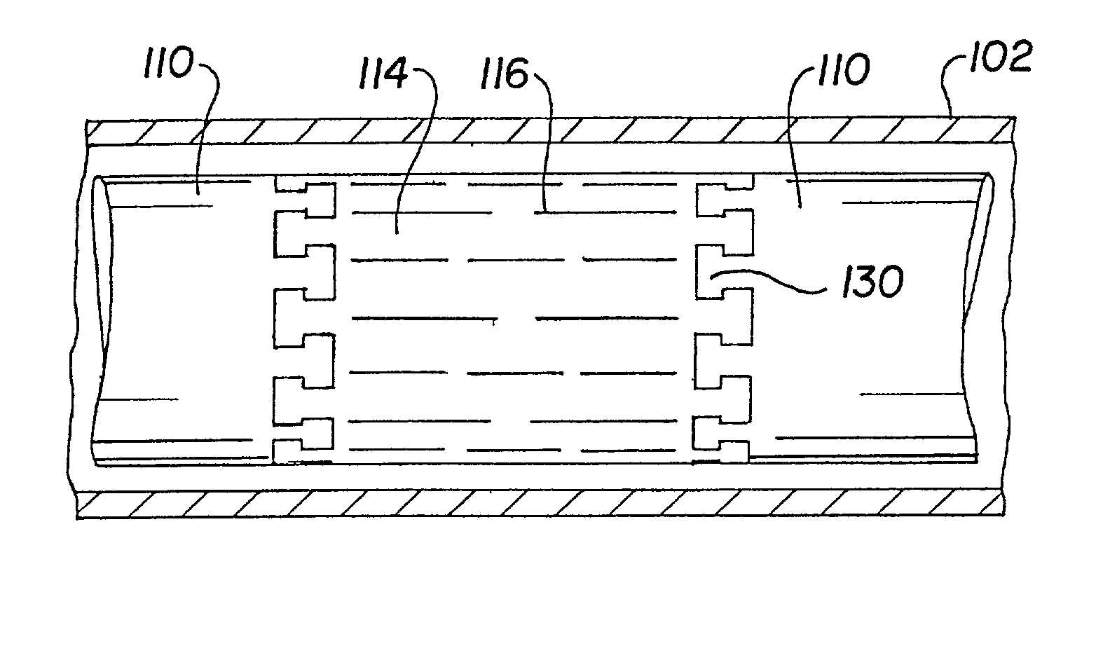
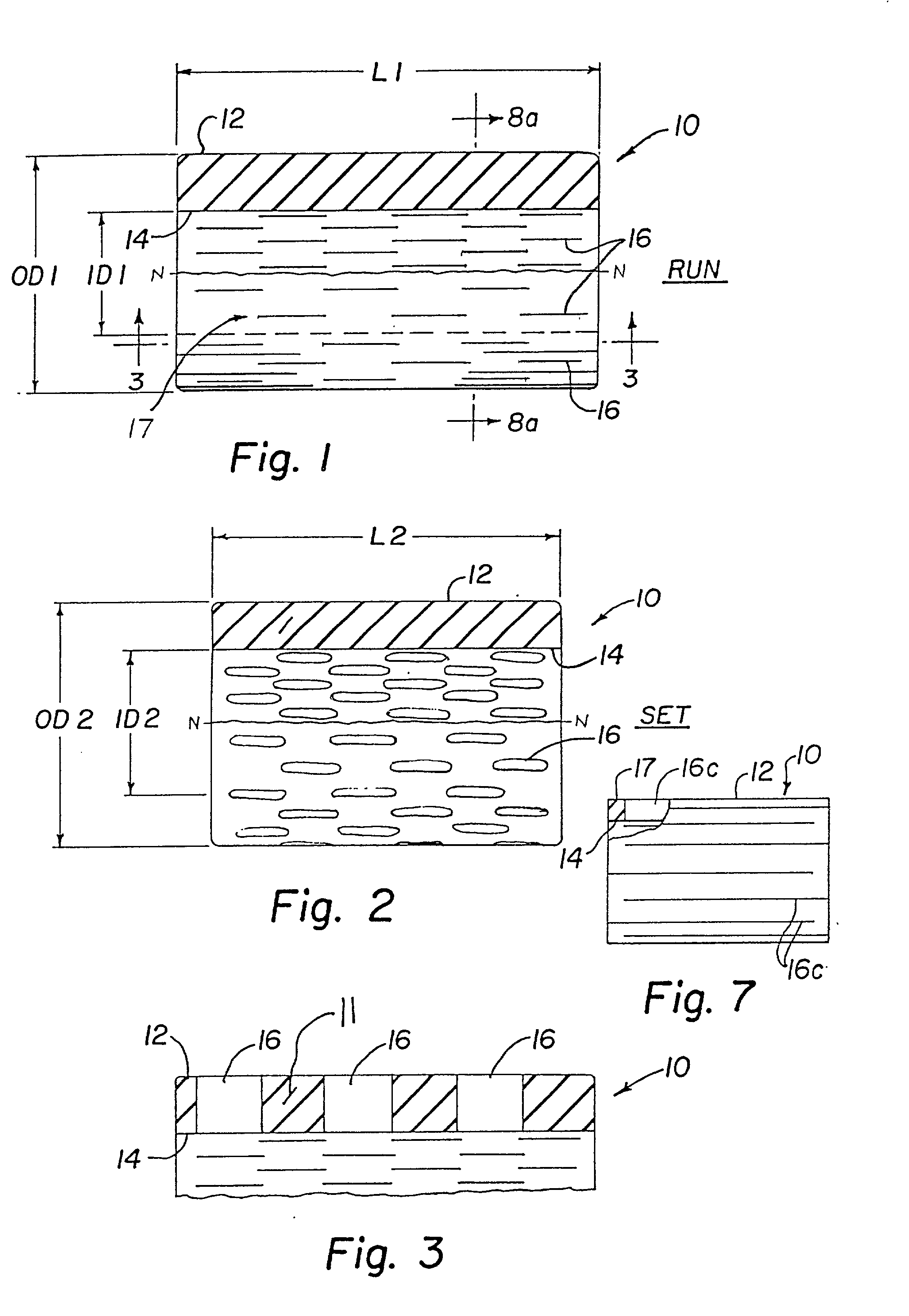
[0031] FIG. 1 is an embodiment of the improved seal element of the present inventions, which for purposes of description is designated by reference numeral 10. Although the improved annular seal configurations of the present inventions have application in a variety of downhole well devices, the following description will by example describe its use in a well packer such as the type shown in U.S. Pat. No. 5,311,938 issued May 17, 1994 entitled "Retrievable Packer For High Temperature, High Pressure Service", which is incorporated herein by reference for all purposes. Seal element 10 would, for example, be used to replace propped seal element 30 in the U.S. Pat. No. 5,311,938 patent. In the illustrated embodiment, the packer elem...


PUM


Abstract

Disclosed is an improved annular well seal elements and method for installing and removing the elements from a subterranean well. The seal element has a plurality of slots formed in the seal element. During radial expansion of the seal element the slots are deformed to reduce hoop stresses in the seal due expansion.

Description

[0001] Not applicable[0002] Not applicableREFERENCE TO MICROFICHE APPENDIX[0003] Not applicable[0004] The present inventions relate to improvements in well seals used for sealing the annulus formed between concentric cylindrical surfaces such as the annulus between a tubing string and the bore of a surrounding casing. More particularly the present inventions relate to improvements in annulus seal elements and the apparatus and methods used to engage and disengage the seal elements.[0005] In the course of treating and preparing subterranean wells for production, frequently seals are utilized to seal an annular spaced formed between concentric cylindrical surfaces. A typical example of the application of an annular seal is present when a well packer is run into the well on a work string, mandrel or production tubing. As used here "packer" is used to describe well apparatus sealing an annular space including but not limited to products sold and referred to in the industry as packers an...

Claims


Application Information

Patent Timeline
IPC IPC(8): E21B33/12E21B33/128E21B43/10F16L55/13
CPCE21B33/1208E21B33/128E21B43/103E21B43/106F16L55/13
Inventor ROSS, COLBY M.
Owner HALLIBURTON ENERGY SERVICES INC
Why Eureka
Try Eureka