Image reader, image forming device, and bearing structure

a technology of bearing structure and drive mechanism, which is applied in the direction of bearing unit rigid support, photosensitive materials, instruments, etc., can solve the problems of impulsive sound, reduced driving efficiency (driving performance decrement), and less durability

Inactive Publication Date: 2003-03-13
RICOH KK
View PDF3 Cites 62 Cited by
  • Summary
  • Abstract
  • Description
  • Claims
  • Application Information

AI Technical Summary

Problems solved by technology

This rattle of the drive shaft 300 causes impulsive sound at the time of start up and stop as well as noise during the normal running due to the load while driving.
If the bearing 202 can not be positioned accurately with respect to the drive shaft 300, a load is exerted on the drive shaft 300 resulting in lower driving efficiency (driving performance decrement) and lesser durability.

Method used


Image

  • Image reader, image forming device, and bearing structure
  • Image reader, image forming device, and bearing structure
  • Image reader, image forming device, and bearing structure

Examples


Embodiment Construction

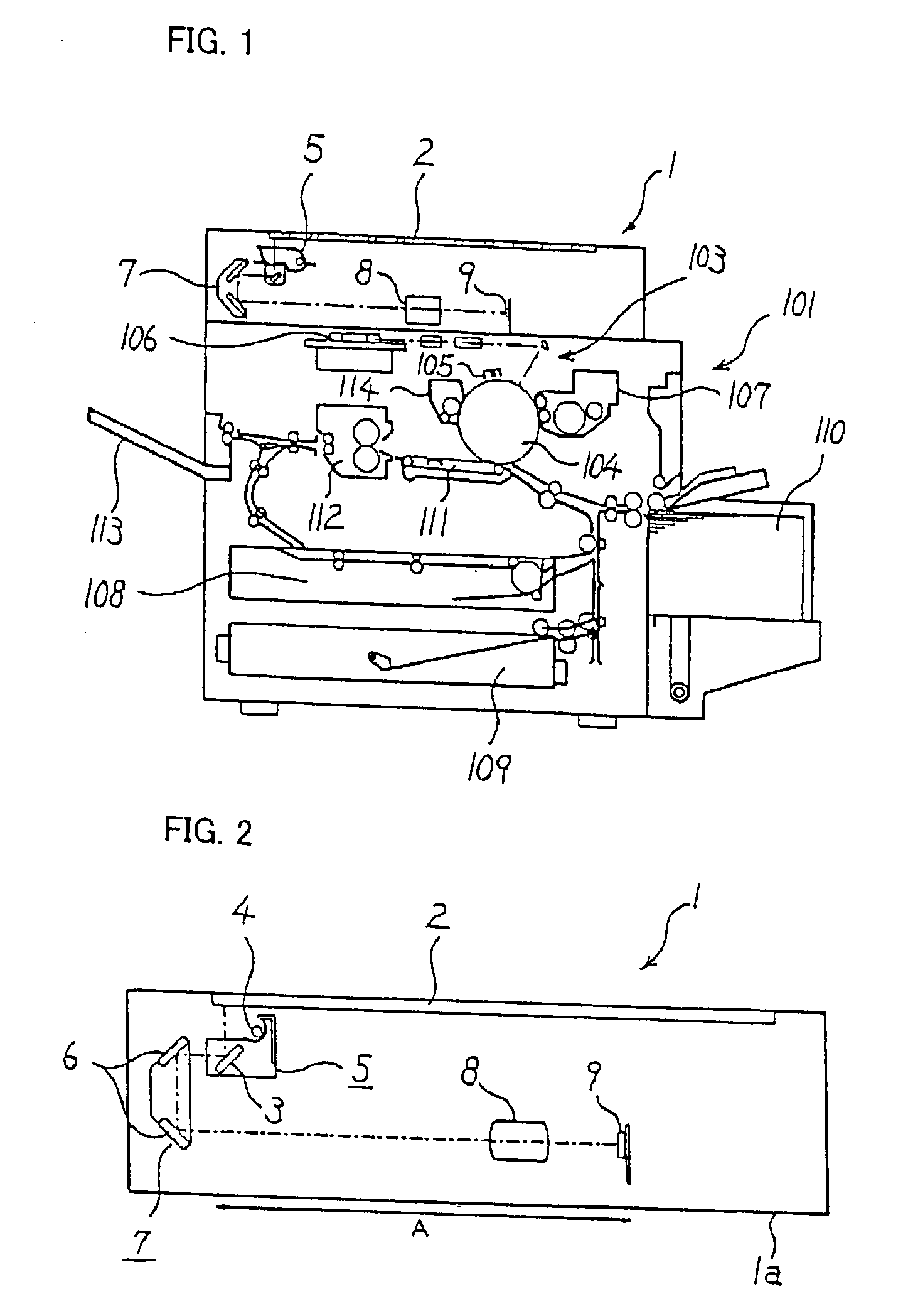
[0026] Embodiments of the present invention are explained below with reference to the accompanying FIG. 1 to FIG. 9. A digital copier is taken as an example of the image forming device, moreover, the scanner in the digital copier is taken as an example of the image reader for the sake of explanation.

[0027] FIG. 1 shows schematically the longitudinal front view of an internal structure of an image forming device 101 with an image reader 1 mounted on it, according to an embodiment of the present invention. The configuration of an image formation section 103, which outputs the image electrophotographically, of the image forming device 101 is widely known. Therefore, the configuration of the image formation section 103 will be explained only briefly.

[0028] In the image formation section 103, the periphery (outer side) of a photoelectric body 104 is charged evenly by a charger 105. Electrostatic latent image is inscribed on the charged part of the photo electric body 104 by a photo inscr...


PUM


Abstract

A drive shaft, which is driven by a drive motor, is held firmly at two points by bearing structures. The bearing structure has a hole in which a bearing member is fit. The bearing member has hole, which is concentric with respect to the hole in which the bearing member is fit. A crimp, which is made of elastic material, having interfering portions that interfere with the bearing member is provided between the bearing member and the hole in the bearing structure in which the bearing member is fit.

Description

[0001] 1) Field of the Invention[0002] The present invention relates to the bearing structure for the drive mechanism, image reader and image forming device equipped with the image reader.[0003] 2) Description of the Related Art[0004] An image reader that scans a surface of a paper (copy surface) and outputs (prints) an image of the copy surface as image data is widely known. In such image readers, a luminous source or a mirror is mounted on the moving body which freely carries out linear reciprocating motion under the contact glass. The light from the illuminant light source is directed on to the copy surface for illuminating it while the moving body is shifted in the secondary (sub) scanning direction along the copy surface mounted onto the contact glass. The light reflected from the copy surface, for every line in the main scanning direction is focused on a charge coupled device (CCD) and made to form an image.[0005] A stepping motor is used to move the moving body. The driving f...

Claims


Application Information

Patent Timeline
Patent Type & Authority Applications(United States)
IPC IPC(8): G03D3/13H04N1/04F16C35/02H04N1/10H04N1/107
CPCG03D3/132
Inventor TAKAHASHI, TAKUJINAGAO, YOSHIAKINISHIKINO, SACHIKO
Owner RICOH KK
Why Eureka
Try Eureka