Device and method for operating a vehicle

Active Publication Date: 2003-03-20
TOYOTA JIDOSHA KK
View PDF4 Cites 27 Cited by
  • Summary
  • Abstract
  • Description
  • Claims
  • Application Information

AI Technical Summary

Problems solved by technology

With this related art, however, operation of the vehicle in accordance with an operation of the operating lever when starting to operate the vehicle is not taken into consideration.
However, because this rotation sensor

Method used


Image

  • Device and method for operating a vehicle
  • Device and method for operating a vehicle
  • Device and method for operating a vehicle

Examples


Embodiment Construction

[0031] In the following description and the accompanying drawings, the invention will be described in more detail in terms of exemplary embodiments.

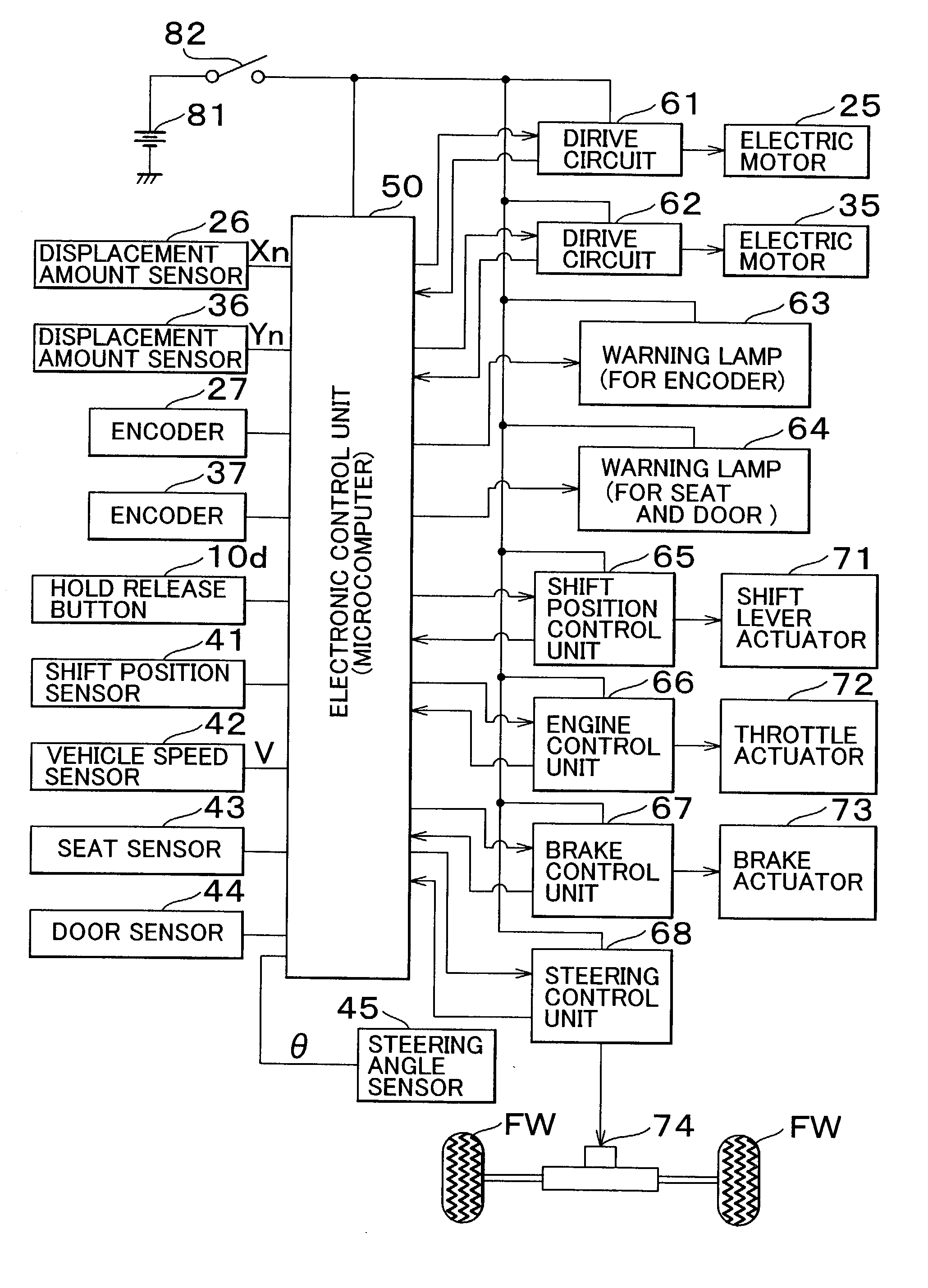
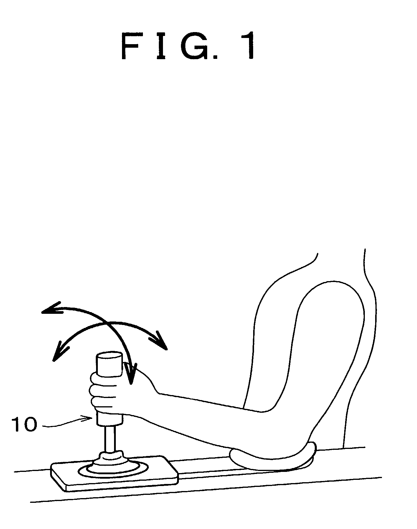
[0032] This device for operating a vehicle includes an operating lever (joystick) 10 which serves as an operating member, as shown in FIG. 1 and FIG. 2. The operating lever 10 is disposed near the driver's seat in the vehicle and is able to tilt (rotate) as a whole unit in a forward-backward direction (direction X) and a left-right direction (direction Y) with respect to the vehicle body, as shown by the arrows in FIG. 1.

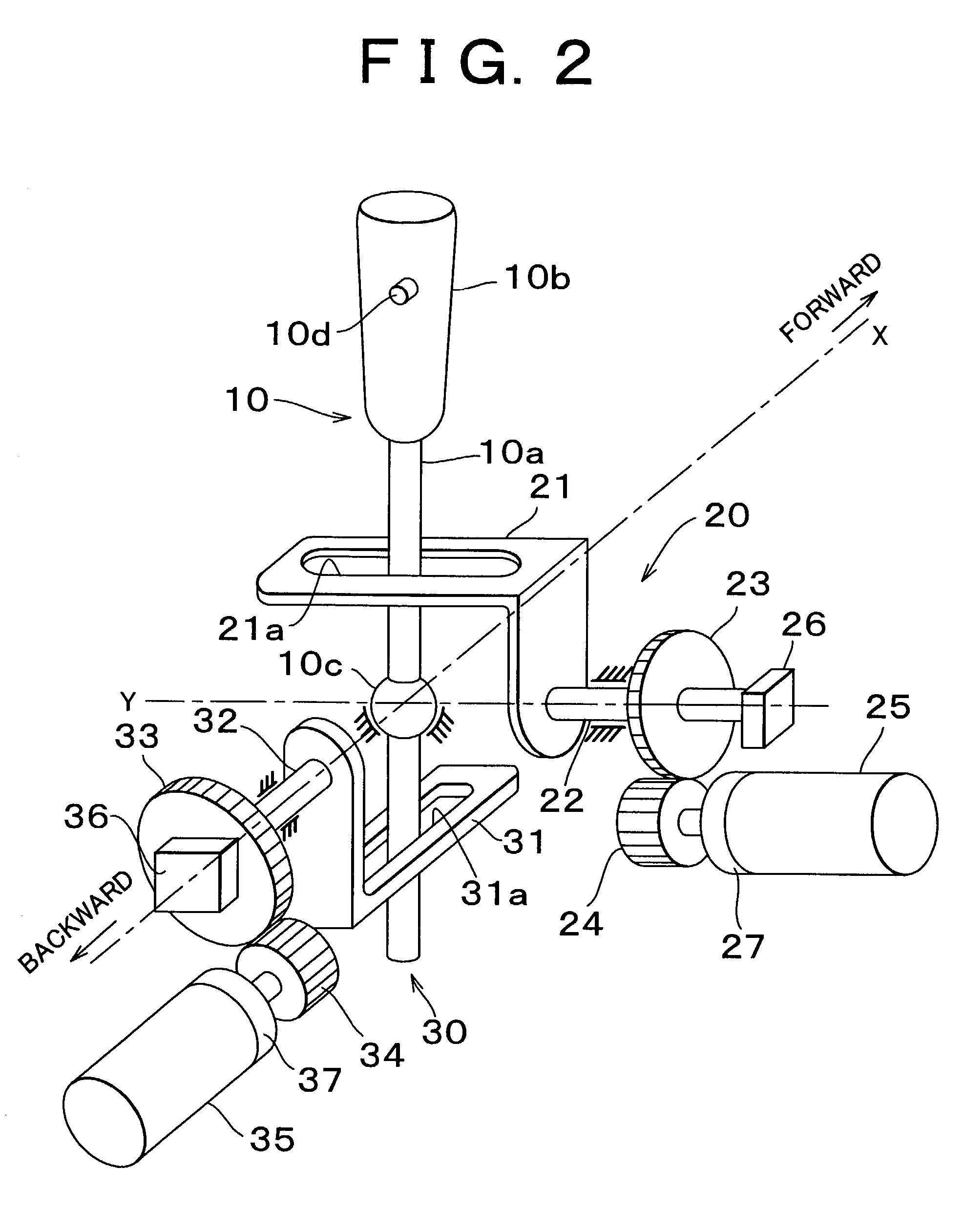
[0033] FIG. 2 shows a schematic perspective view of an operating lever device which includes the operating lever 10. The operating lever 10 includes a rod 10a and a cylindrical gripping portion 10b that is fixed to the outer periphery of an upper portion of the rod 10a. The rod 10a includes a ball shaped portion 10c and is rotatably supported by this ball shaped portion 10c in the left-right and forward-backward directio...


PUM


Abstract

A device and method for operating a vehicle having an operating member that is displaceable with respect to a vehicle body and operated by a driver, controls an acceleration of the vehicle according to a displacement position of the operating member, displaces the operating member to a predetermined initial position when electric power starts to be supplied, and prohibits acceleration of the vehicle according to a displacement position of the operating member when the operating member is being displaced to the initial position until the operating member reaches a position which does not instruct the vehicle to accelerate. With this type of device for operating a vehicle, it is possible to prevent the vehicle from moving against the wishes of the driver at the start of operation.

Description

INCORPORATION BY REFERENCE[0001] The disclosure of Japanese patent application no. 2001-279352 filed on Sep. 14, 2001, including the specification, drawings and abstract is incorporated herein by reference in its entirety.[0002] 1. Field of Invention[0003] The invention relates to a device and method for operating a vehicle according to an operation by a driver of an operating member which is able to be displaced with respect to a vehicle body.[0004] 2. Description of Related Art[0005] A device for operating a vehicle, which is provided with an operating lever supported so as to be able to be displaced (tilted) with respect to the vehicle body, in which the vehicle is steered and accelerated according to a displacement position of the operating lever operated by the driver has been known. An example of this type of art is disclosed in Japanese Patent Application Laid-Open Publication No. 8-142873 and Japanese Patent Application Laid-Open Publication No. 8-34353. This type of device ...

Claims


Application Information

Patent Timeline
IPC IPC(8): B60K23/00B60K26/02B60K28/00B60L15/10B60R16/02B60T7/10B60W10/04B60W10/06B60W10/18B60W10/184B60W10/20B62D1/12F02D9/02F02D11/10F02D29/02F02D41/06F02D41/22F02D45/00G05G5/03G05G9/047G05G25/00
CPCB60K2741/20B60L15/10B60T7/085Y02T10/648B60W30/18181B62D1/12Y02T10/646B60T7/10B60W10/04B60W10/18Y02T10/64
Inventor YANAKA, AKIHIRO
Owner TOYOTA JIDOSHA KK
Why Eureka
Try Eureka