Engine compartment structure of a work machine

a technology for work machines and engine compartments, applied in the direction of machines/engines, snow cleaning, tractors, etc., can solve the problems of difficult to improve cooling efficiency, high temperature inside the engine compartment, complex inside the engine compartment structure,

Inactive Publication Date: 2003-04-10
KOMATSU LTD
View PDF10 Cites 35 Cited by
  • Summary
  • Abstract
  • Description
  • Claims
  • Application Information

AI Technical Summary

Problems solved by technology

However, in the former (Japanese Patent Application Laid-Open No. 2001-27130) of the above mentioned prior arts, since the engine compartment is covered by the shielding plate in a sealed state, the temperature inside the engine compartment becomes high due to a heat generation of the engine.
Accordingly, since the engine speed gets high and the engine generates more heat, it is hard to improve the cooling efficiency.
Further, it is requir

Method used


Image

  • Engine compartment structure of a work machine
  • Engine compartment structure of a work machine
  • Engine compartment structure of a work machine

Examples


Embodiment Construction

[0034] Preferred embodiment in accordance with the present invention will be described in detail with reference to the accompanying drawings.

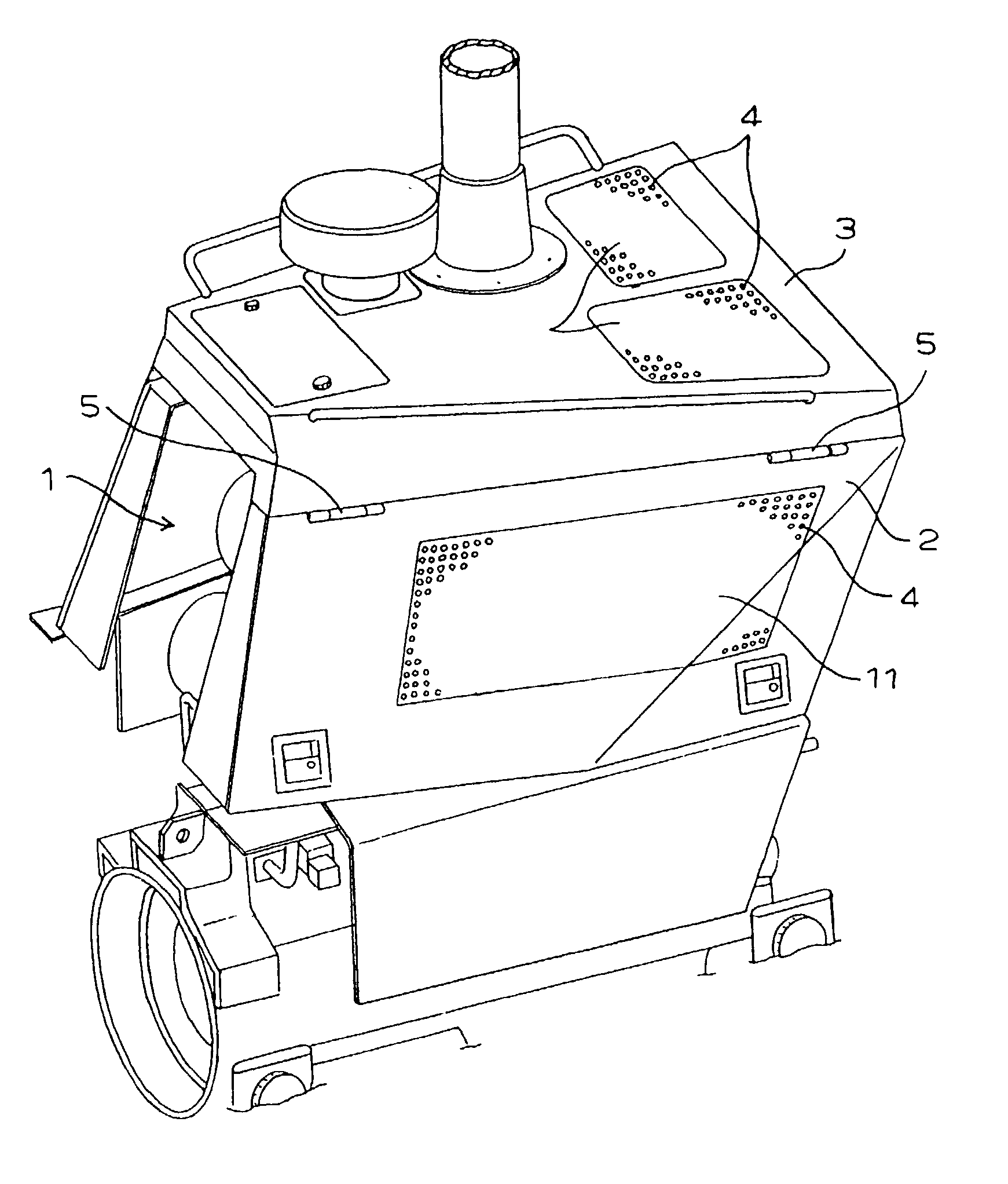
[0035] FIG. 1 schematically shows a perspective view of side covers 2 and a hood 3 which cover an engine compartment 1. The side covers 2, which are on right and left sides, can be opened and closed respectively by hinges 5. The side cover 2 is attached with a metal plate 11, which is provided with a plurality of punch holes to form vents 4. In place of the punch holes, the vents may be a metal plate which is formed with a plurality of slit-like opening portions, or a mesh sheet material. Further, in place of using the metal plate, punch holes or slit-like opening portions may be formed directly on the side cover 2.

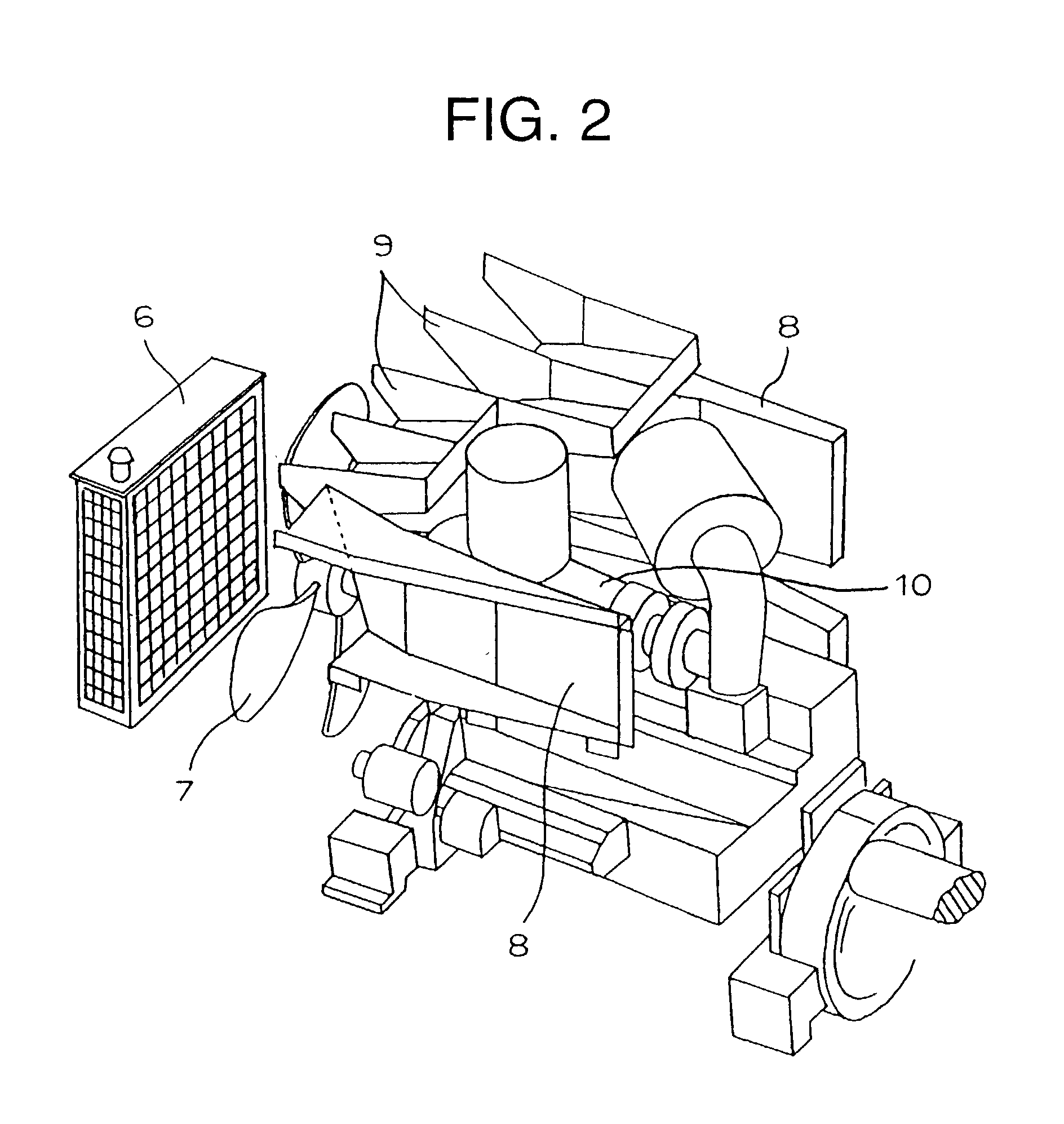
[0036] FIG. 2 schematically shows a perspective view of the inside of the engine compartment 1 from which the side covers 2 and the hood 3 are taken away. An engine 10 and the other devices are arranged within the engine compartment ...


PUM


Abstract

In a structure of an engine compartment in a work machine such as a tractor, a bulldozer, a hydraulic excavator, a wheel loader, the air taken through vents, which are formed on side covers and a hood covering the engine compartment, is supplied directly to a radiator via ducts which are provided on the side of the side covers and the side of the hood respectively. The ducts cover the vents, thereby preventing noise within the engine compartment from escaping to the outside. Therefore it is possible to increase a cooling efficiency of the radiator by supplying the outside air, which does not take up the heat of an engine, directly to the radiator, as well as to reduce the engine sound and prevent the engine noise from escaping.

Description

BACKGROUND OF INVENTION[0001] 1. Field of the Invention[0002] The present invention relates to a structure of an engine compartment in a work machine, for example, a tractor, a bulldozer, a hydraulic excavator, a wheel loader and the like. More particularly, it relates to the structure which is capable of improving a cooling efficiency with respect to a radiator, reducing an engine sound and preventing a noise from the engine compartment.[0003] 2. Description of the Related Art[0004] In general, such a structure of the inside of an engine compartment in a work machine has been known that a radiator and an oil cooler are arranged in a front portion of the engine or the like for cooling the radiator and the oil cooler by a cooling fan. The cooling fan is directly driven by means of a belt drive or the like by the engine, or is driven by an electric motor or a hydraulic motor, which is rotated and controlled independently of the engine rotation. For the cooling of a radiator, an oil co...

Claims


Application Information

Patent Timeline
IPC IPC(8): B60K11/08E02F9/00B62D49/00F01P5/06F01P11/10F02B77/13
CPCB60Y2200/41B60K11/08
Inventor TAKEZAKI, GIIKUNAGAHIRO, YUICHI
Owner KOMATSU LTD
Why Eureka
Try Eureka