Spark plug

a technology of spark plugs and spark plugs, which is applied in the direction of spark plugs, sparking plugs, basic electric elements, etc., can solve the problems of reducing the area from which the fuel droplet suspends, accumulating fuel in the liquid state of pistons, and undetectable degrading the startability contrary to expectations

Inactive Publication Date: 2003-04-17
NGK SPARK PLUG CO LTD
View PDF2 Cites 28 Cited by
  • Summary
  • Abstract
  • Description
  • Claims
  • Application Information

AI Technical Summary

Problems solved by technology

Suction of a fuel-air mixture of higher concentration aiming at improving the startability at lower temperature, however, tends to cause accumulation of the fuel in a liquid state within pistons.
The fuel-air mixture after sucked into a combustion chamber will therefore not be ignited, which undesirably degrade the startability contrary to expectation.
Such constitution is disadvantageous in reducing the area from which the fuel droplet suspends, since the length of the straight rod portion which composes the end portion of the center electrode must be excessively long, and the divergent portion which extends from the straight rod portion must be narrow.
This adversely affects the heat radiation from the straight rod portion and tends to promote the wear thereof due to spark discharge.
And what is more, the tendency of the wear due to spark discharge is strong, since the area of the end face of the ground electrode cannot be set as to be so large.
Even if the fuel-air mixture is once ignited by electric spark generated in the spark discharge gap, the electrode which resides in the vicinity of the ignited fuel-air mixture takes the heat away, which results in flame-out of the fuel-air mixture.
On the contrary, a width of coverage K exceeding 0.5 mm herein may undesirably accelerate wear of the ground electrode due to overheat.
If the area of the end face of the protruded portion is smaller than that of the center electrode, the adhesive force, which is expressed between the center electrode and droplet when the fuel bridge is formed, will exceed the gravity effected to such droplet, which may make it difficult to rupture the fuel bridge.
The ground electrode will thus have only a limited range of wear, but is likely to be heated as compared to the center electrode since it is located more closer to the center of the combustion chamber, and may suffer from accelerated wear depending on the types of internal combustion engines.
When the cranking is sustained thereafter, the generated vibration will cause drop-off of the adhered fuel from the outermost side of the end portion of the insulator.

Method used


Image

  • Spark plug
  • Spark plug
  • Spark plug

Examples


examples

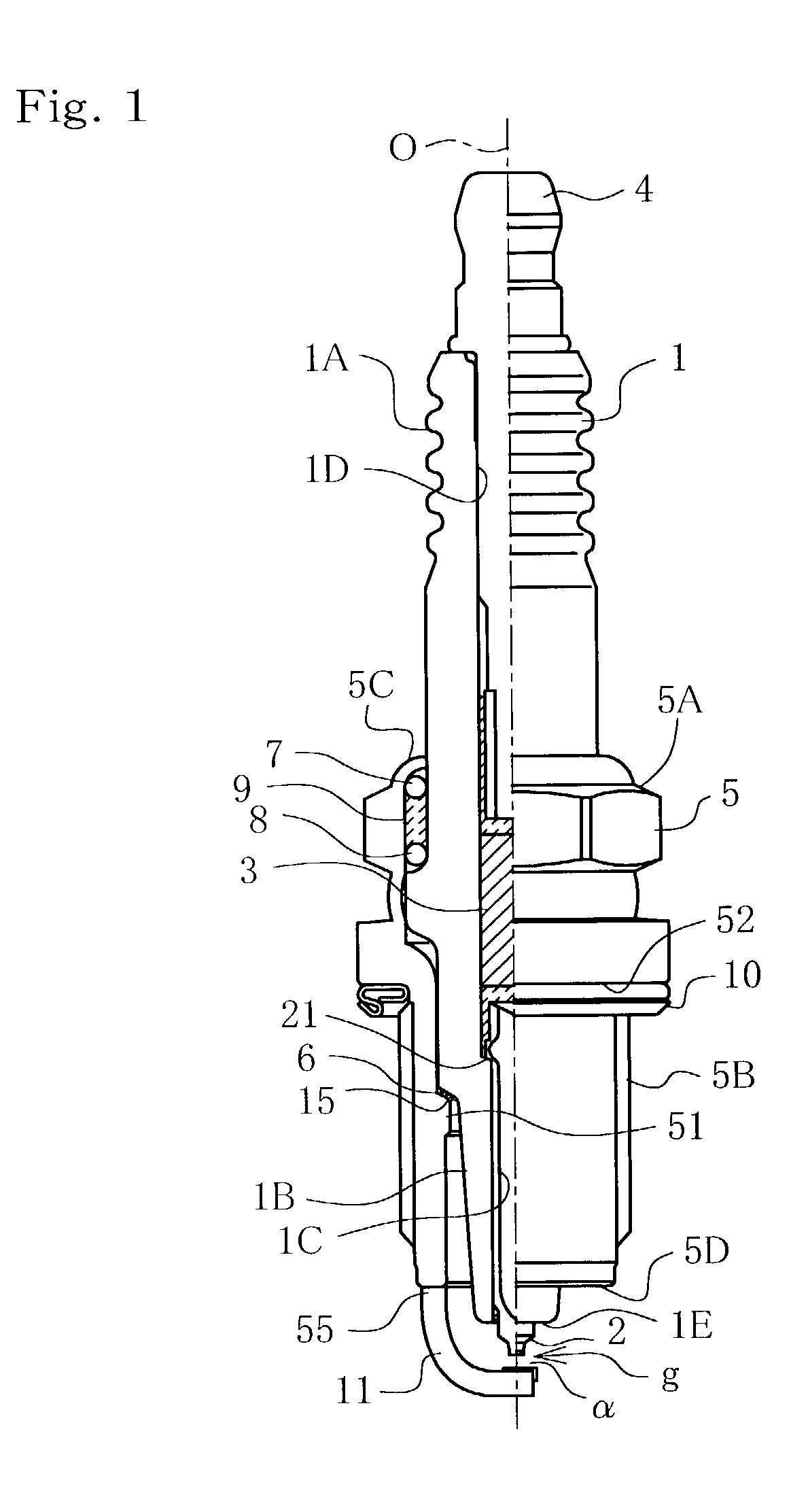
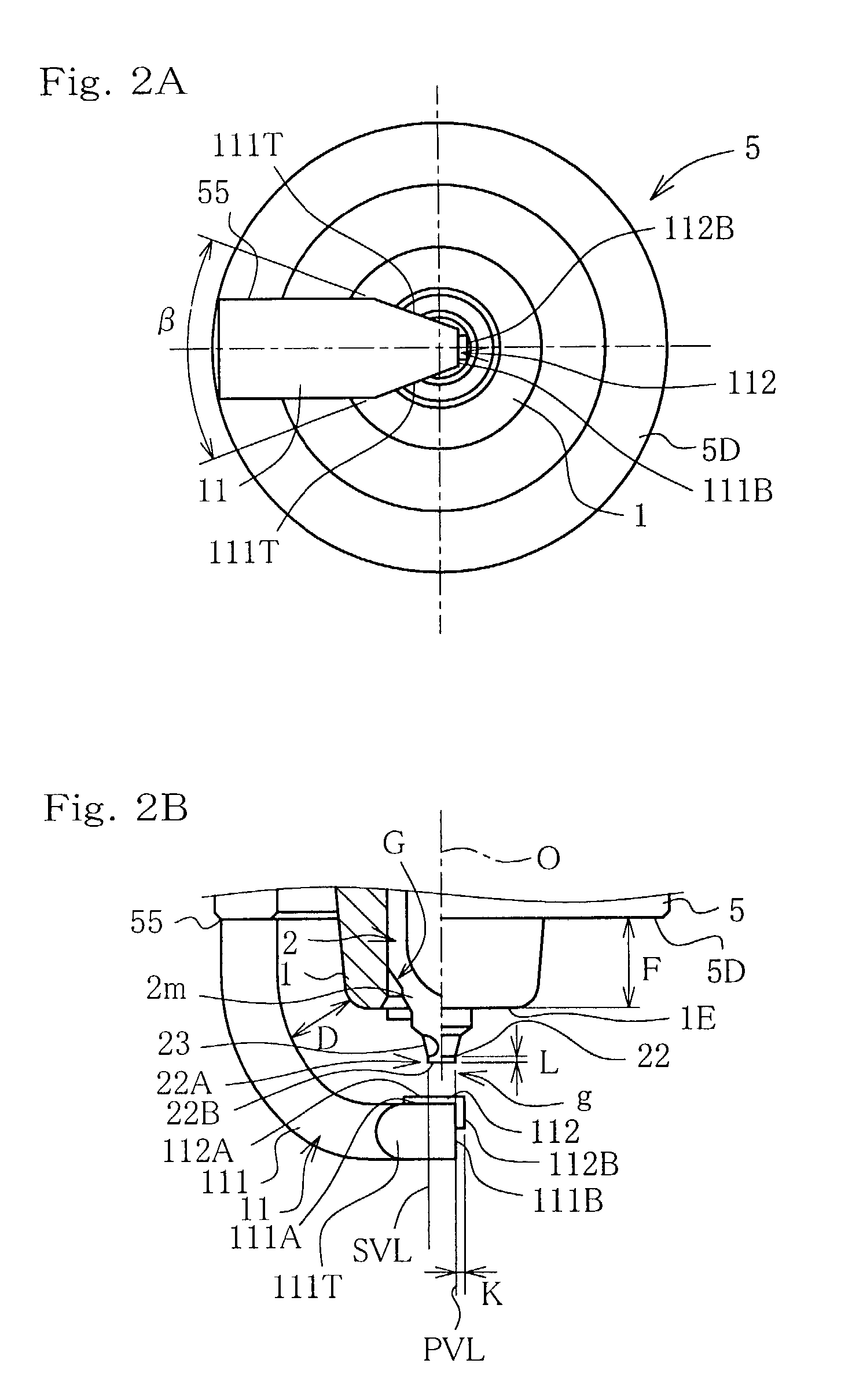
[0061] Experiments for demonstrating effects of the present invention will be described below. Sample Nos. {circle over (1)} to {circle over (4)} shown in FIG. 8 represent samples according to the embodiments of the present invention, and No. {circle over (5)} represents a comparative example for confirming difference in the effects from those of the samples of the present invention. As for the samples according to the individual embodiments, the description is limited only to points differing from those for the first embodiment. The sample {circle over (1)} according to the first embodiment is such that having the essential portion of which already been shown as being enlarged in FIGS. 2A and 2B. FIG. 2B is a side elevation solely showing the ignition portion of the sample {circle over (1)}, and FIG. 2A is a bottom view of FIG. 2B. The sample {circle over (2)} according to the second embodiment is shown in FIGS. 3A to 3C, which are enlarged views for the principal portion of the sa...


PUM


Abstract

A spark plug is disclosed, in which a center electrode has, at the end thereof which forms a spark discharge gap, a noble metal chip which has a straight rod portion of 1.0 mm or less in diameter and 0.2 mm or more in length; width of coverage K of a ground electrode on which a rectangular noble metal chip is welded satisfies a relation of -d<=K<=0.5 mm (where, d represents the diameter of the end face of the center electrode); and width w of a portion of the discharge plane 111A which falls within a range corresponded to the axial extension of the end face 22B of the noble metal chip 22 provided on the center electrode 2 satisfies a relation of w<2.1-K (in mm), where K is the foregoing width of coverage.

Description

[0001] The present invention relates to a spark plug available as an ignition device for internal combustion engine, and more specifically to a spark plug capable of promoting rupture of fuel bridge if it should occur so as to fill a spark discharge gap, to thereby successfully suppress degradation in the ignition property.DESCRIPTION OF THE BACKGROUND ART[0002] Conventional spark plug generally comprises a center electrode protruded downward from the end face of an insulator, and a ground electrode joined at one end thereof to a metal shell, and is composed so as to form a spark discharge gap between the end face of the center electrode and ground electrode, where electric spark generated in the gap ignites mixed fuel gas. To improve startability of the spark plug at low temperature, it has been a general practice for internal combustion engine to raise concentration of fuel-air mixture sucked into a combustion chamber.[0003] Suction of a fuel-air mixture of higher concentration ai...

Claims


Application Information

Patent Timeline
Patent Type & Authority Applications(United States)
IPC IPC(8): H01T13/20H01T13/39
CPCH01T13/39H01T13/20
Inventor TERAMURA, HIDEKIMUSASA, MAMORUKAGAWA, JUNICHI
Owner NGK SPARK PLUG CO LTD
Why Eureka
Try Eureka