LCD monitor stand

Inactive Publication Date: 2003-04-24
SAMSUNG ELECTRONICS CO LTD
View PDF14 Cites 91 Cited by
  • Summary
  • Abstract
  • Description
  • Claims
  • Application Information

AI Technical Summary

Benefits of technology

0022] FIG. 8 is a perspective view of the conventional LCD monitor stand; and
0023] FIG. 9 i

Problems solved by technology

However, in this configuration, because a cable that allows communication between the LCD monitor 3 and a computer (not shown), a power cable, and other similar components a

Method used


Image

  • LCD monitor stand
  • LCD monitor stand
  • LCD monitor stand

Examples


Embodiment Construction

[0024] Embodiments of the present invention will be described in more detail with reference to the accompanying drawings, wherein like reference numerals refer to the like elements throughout.

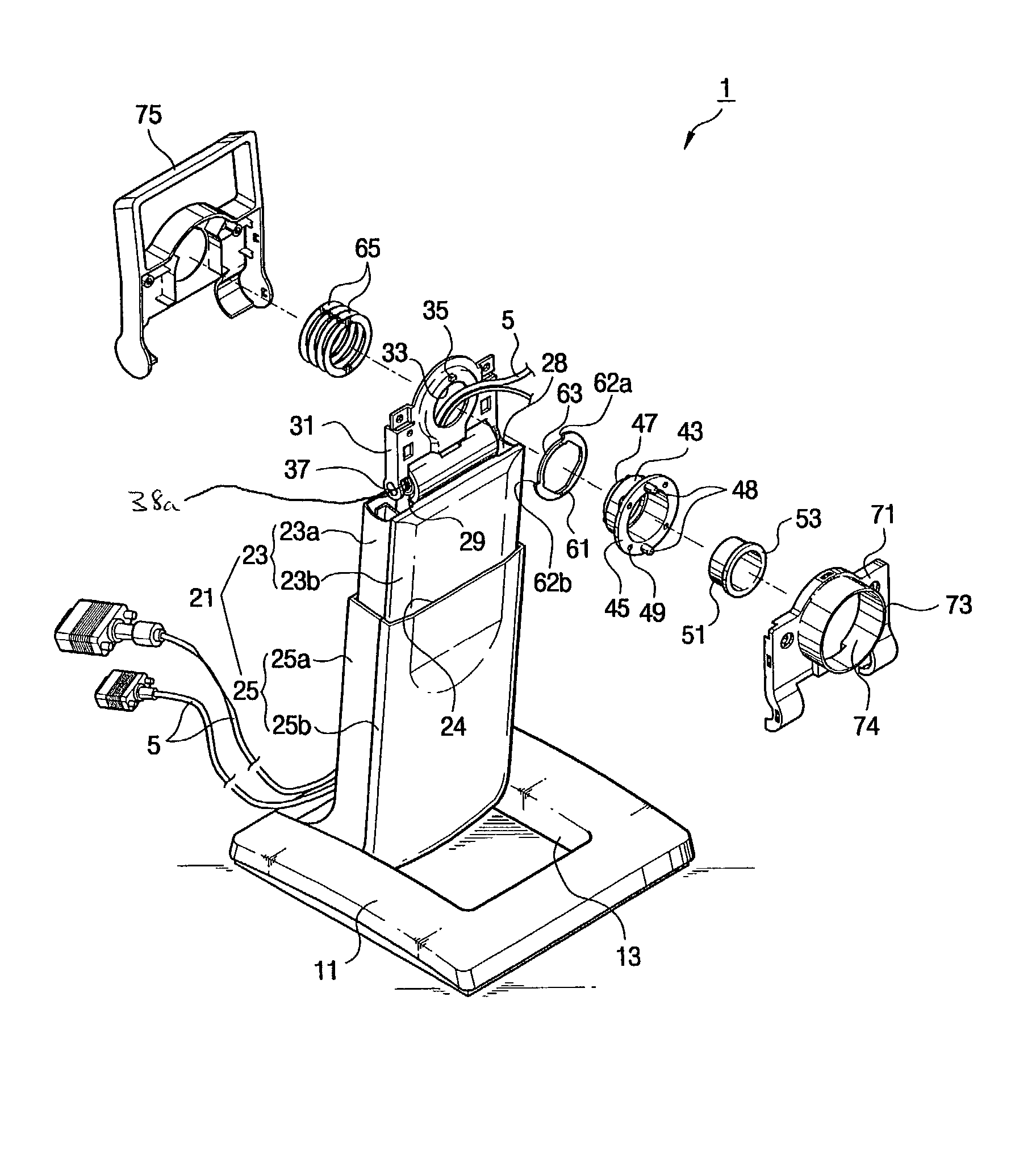
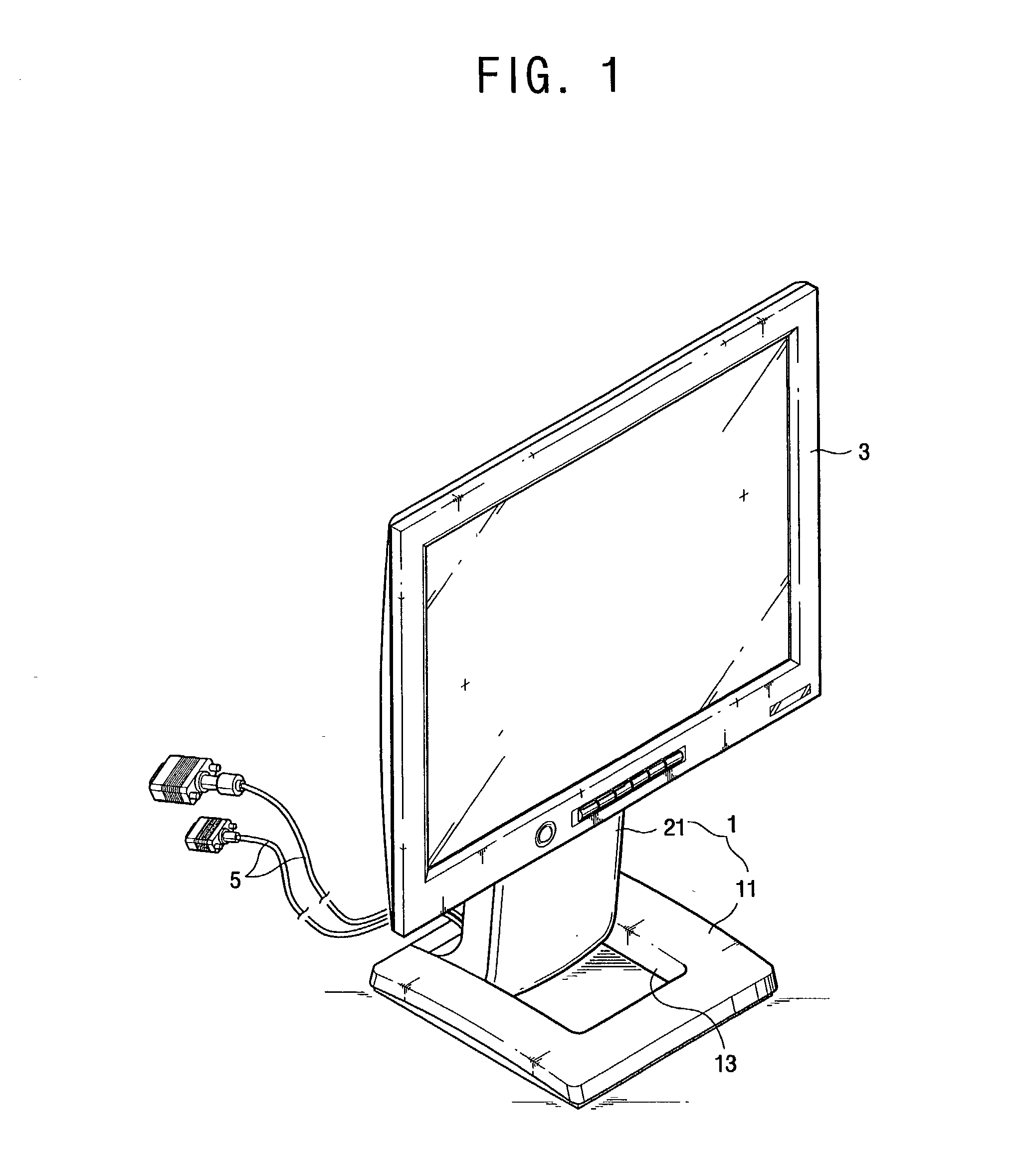
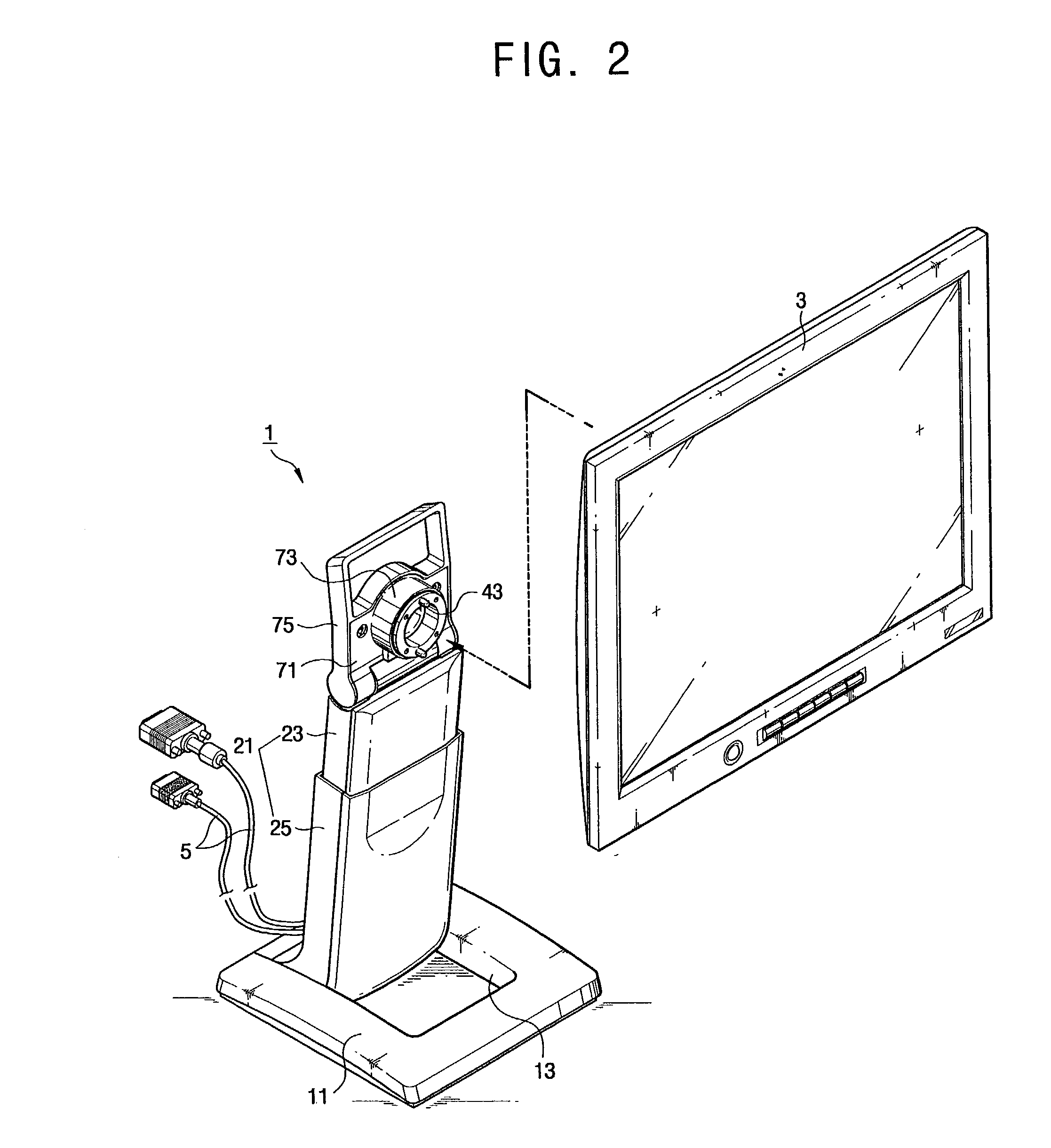
[0025] As shown in FIGS. 1 and 2, an LCD monitor stand 1 according to an embodiment of the present invention includes a base part 11 and a stand part 21 that supports the LCD monitor 3. Further, as shown in FIG. 4, the LCD monitor stand 1 additionally comprises a first rotation member 31 to allow vertical rotation about a first horizontal axis, and a second rotation member 41 to allow planar rotation about an axis of rotation. The first and second rotation members 31 and 41 are installed at an upper end part of the stand part 11.

[0026] The base part 11 has a generally rectangular shape, and has an opening 13 at the center area thereof. At the rear of the opening 13 is mounted the stand part 21. Further, on the bottom of the base part 11 is provided a swivel device (not shown) to allow the base ...


PUM


Abstract

An LCD monitor stand includes a base part, a stand part to stand on the base part and having a cable accommodating part to accommodate cables therein, a hinge shaft positioned across a standing direction of the stand part, a first rotation member to rotate up and down on the hinge shaft, and a second rotation member rotatably coupled to the first rotation member, to rotate the LCD monitor in a planar direction. With this configuration, it is possible to apply tilting and pivoting structures to the internal cable type LCD monitor.

Description

[0001] This application claims the benefit of Korean Application No. 2001-65741, filed Oct. 24, 2002, in the Korean Intellectual Property Office, the disclosure of which is incorporated herein by reference.[0002] 1. Field of the Invention[0003] The present invention relates in general to an LCD monitor stand, and more particularly, to an LCD monitor stand having an internal cable.[0004] 2. Description of the Related Art[0005] An LCD monitor stand supporting an LCD monitor is classified into an external cable type and an internal cable type. As shown in FIG. 8, an external cable type LCD monitor stand 101 has a tilt member 115 and a pivot member 117, which are disposed between a main body 105 and an LCD monitor (such as the LCD monitor 3 shown in FIG. 1). The tilt member 115 is installed at the upper part of the main body 105 and rotates up and down about a first horizontal axis. The pivot member 117 is combined to the LCD monitor 3 and rotates against the tilt member 115 about a sec...

Claims


Application Information

Patent Timeline
IPC IPC(8): F16M11/12F16M11/24G06F1/16
CPCF16M11/105F16M11/12F16M11/2064F16M11/24F16M11/28Y10S248/924Y10S248/919Y10S248/921Y10S248/922Y10S248/92Y10S248/923F16M2200/041G06F1/16
Inventor JEONG, JUN-SOOLEE, HI-TAEK
Owner SAMSUNG ELECTRONICS CO LTD
Why Eureka
Try Eureka